v 2 Ethernet icon
v 3 System-locator button and LED (blue)
v 4 Release latch for the light path diagnostics panel
v 5 Ethernet activity LEDs
v 6 Check log LED
v 7 System-error LED: (yellow)
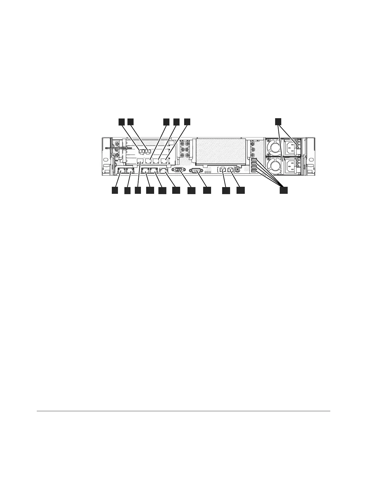
Figure 21 identifies the various ports and hardware in the rear of the file module:
v 1 8 Gbps Fibre Channel port 1 (connected to the control enclosure)
v 2 8 Gbps Fibre Channel port 2 (connected to the control enclosure)
v 3 Ethernet port 8
v 4 Ethernet port 9
v 5 Ethernet port 10
v 6 Power supplies(1islower 2 is upper)
v 7 Ethernet port 1 (connected to the other file module)
v 8 Ethernet port 2 (connected to the other file module)
v 9 Ethernet port 7
v 10 Ethernet port 3
v 11 Ethernet port 4
v 12 Systems-management Ethernet port (NOT USED)
v 13 Video port
v 14 Serial port
v 15 Ethernet port 5 (10 Gbps)
v 16 Ethernet port 6 (10 Gbps)
v 17 USB ports
Miscellaneous hardware
The USB flash drive is packaged with the publications and contains the
initialization tool for performing the initial system configuration.
Verifying environmental requirements
Certain requirements for the physical site must be met to ensure that your system
works reliably.
1
2
3
4
5
6
17
6
1
2
3
4
5
10
7
8
9
11
12
13
14
15
16
ifs00063
Figure 21. Rear view of 2073-720 file module
50 IBM Storwize V7000 Unified: Adding Storwize V7000 File Modules to an existing Storwize V7000 system 2073-720
 Loading...


