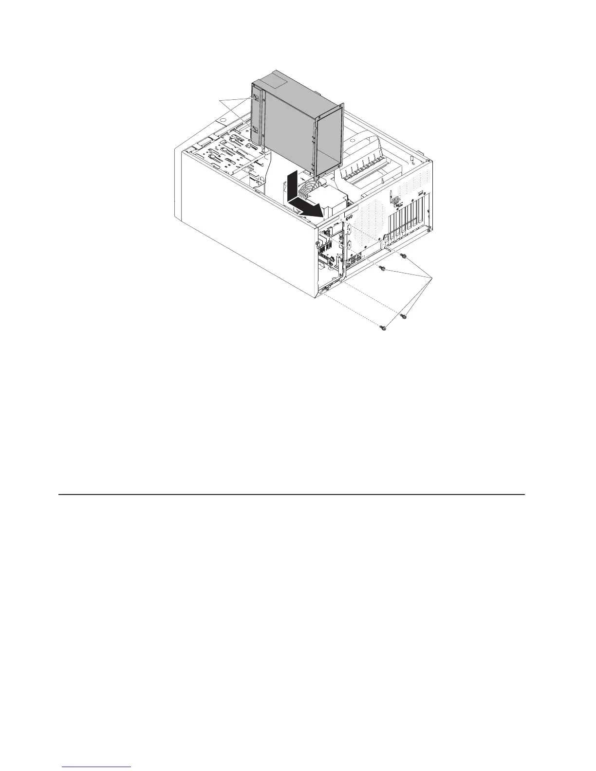
Retaining
clips
Screws
2. Install the other two screws to further secure the power-supply cage to the
chassis, which is located in front of the power-supply cage.
3. Connect the cables from the power-supply cage to the system board and all
internal components (see “System-board internal connectors” on page 17 for the
locations of the internal connectors).
4. Stand the server back up in its vertical position.
5. Reinstall the hot-swap power supplies (see “Installing the hot-swap power
supply” on page 245).
6. Install and lock the side cover (see “Installing the side cover” on page 167).
7. Reconnect the external cables and power cords; then, turn on the attached
devices and turn on the server.
Removing and replacing FRUs
Field replaceable units (FRUs) must be installed only by trained service technicians.
Removing the microprocessor and heat sink
To remove the microprocessor and heat sink on 4U server models with
non-hot-swap power supplies, complete the following steps. For the 5U server
model with hot-swap power supplies (Model name: 2582-F4x), please see the next
sub-section.
1. Read the safety information that begins on page vii and “Installation guidelines”
on page 163.
2. Turn off the server and all attached devices; then, disconnect all power cords
and external cables.
3. Carefully turn the server on its side so that it is lying flat, with the cover facing
up.
Attention: Do not allow the server to fall over.
4. Remove the side cover (see “Removing the side cover” on page 166).
250 IBM System x3100 M4 Type 2582: Problem Determination and Service Guide