Before you disconnect the power source, make a note of which LEDs are lit,
including the LEDs that are lit on the operation information panel and LEDs inside
the server on the system board.
Table 3. System board LEDs
Component LED Description
DIMM error LEDs A memory DIMM has failed or is incorrectly installed.
Microprocessor/CPU error LED Microprocessor has failed, is missing, or has been incorrectly installed.
Note: (Trained service technician only) Make sure that the
microprocessor is installed in the correct sequence; see “Installing a
microprocessor and heat sink” on page 254.
System board error LED System-board CPU VRD and/or power voltage regulators have failed.
IMM heartbeat LED Indicates the status of the boot process of the IMM2.
When the server is connected to power this LED flashes quickly to
indicate that the IMM2 code is loading. When the loading is complete,
the LED stops flashing briefly and then flashes slowly to indicate that
the IMM2 if fully operational and you can press the power-control
button to start the server.
RTMM heartbeat LED Power-on and power-off sequencing.
Standby power LED When this LED is lit, it indicates that the server is connected to ac
power.
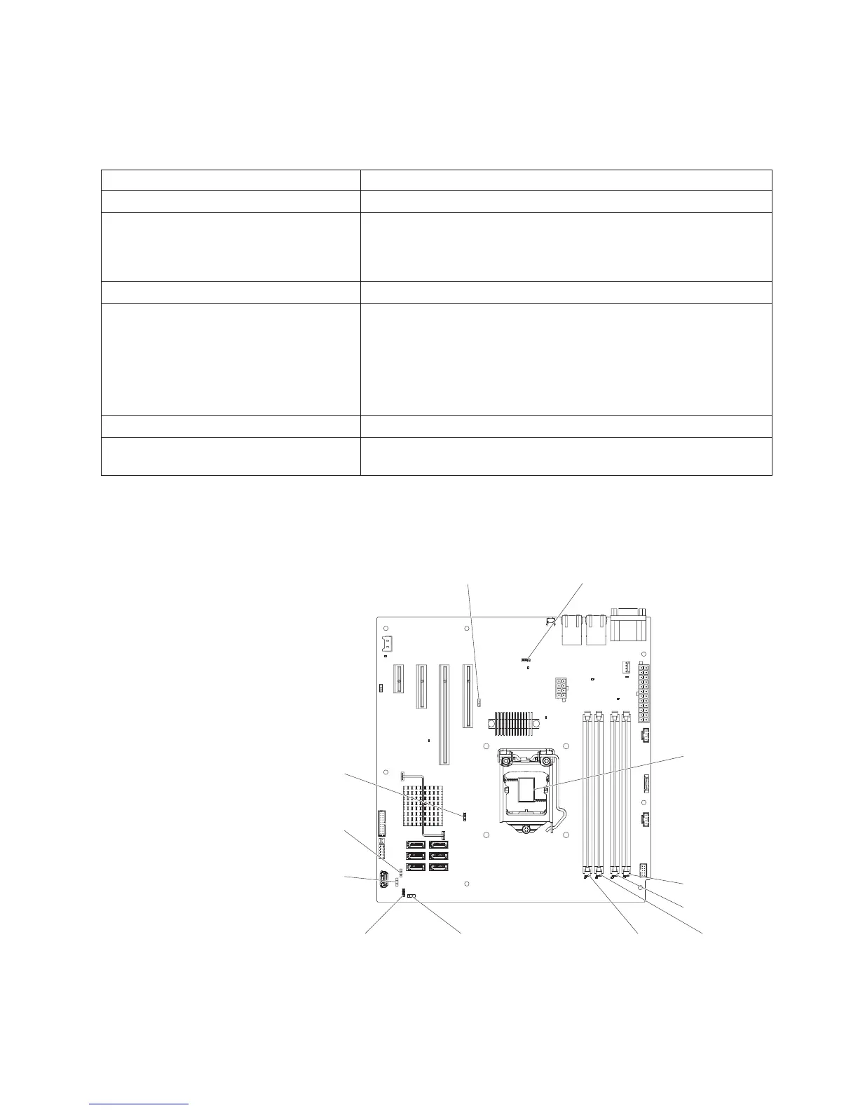
System-board switches and jumpers
The following illustration shows the jumpers on the system board.
Clean CMOS
jumper (JP1)
BIOS boot backup
jumper (JP2)
ME recovery
jumper (JP8)
ME flash
override
jumper(JP9)
TPM initialization
jumper (JP11)
Low security_N
jumper (JP22)
IMM SPI half
ROM enable (JP12)
DIMM 1 slot
DIMM 2 slot
DIMM 3 slotDIMM 4 slot
Microprocessor
Chapter 2. Introduction 19
 Loading...