3 - 1
SECTION 3 CIRCUIT DESCRIPTION
3-1 RF UNIT
The RF UNIT is composed by BPFs for both TX and RX,
attenuator and pre-AMP for RX line, YGR AMP, SWR detect
circuit and ALC circuit for TX line.
• TX/RX SW
RL1 connects the RX/TX circuit to the antenna connector
according to the operation (receiving/transmitting).
While receiving, RL1 connects the antenna connector and
the attenuator through the LPF. While transmitting, RL1
connects the antenna connector and J10 which guides the
TX signal from the FILTER UNIT.
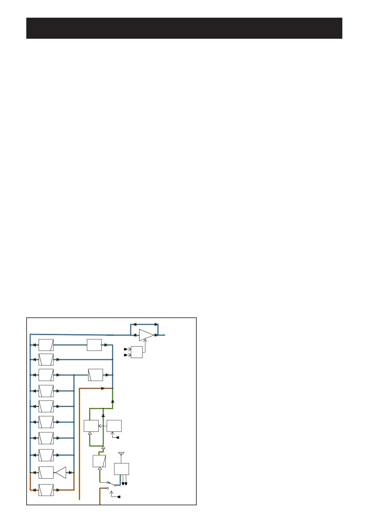
• ATTENUATOR (ATT)
The attenuator is composed of D164, D165, R163 and
R164.
While the ATT function is inactivated, D164 turns ON and
D165 turns OFF to apply the RX signals to next RX stage
via D164 without attenuation.
While the ATT function is activated, D164 turns OFF and
D165 turns ON and the RX signals are divided by R163 and
R164 for 20 dB of attenuation.
• BPF
The RX signals from the ATT are passed through one of
9 BPFs. The BPF for MF band contains an attenuator to
prevent the saturation caused by strong RX signals. The
BPF for 50 MHz band contains a pre-AMP (Q380) to make
up the loss for high sensitivity.
These BPFs are commonly used in TX and RX, but
exclusive BPF for 50 MHz TX is also equipped to secure the
transmit signal path for 50 MHz.
• PRE-AMP
While the pre-amp. function is activated, the RX signals
from the BPF are applied to the noiseless feedback AMP
(Q441). This AMP provides low-noise, high RF gain and
good IP characteristic. The amplified RX signals are entered
to the MAIN UNIT via J7.
• YGR AMP
While TX, the transmit signal (YGR signal) is entered to the
MAIN UNIT via J7. The transmit signal is by-passed the pre-
AMP and passed through one of BPFs, and amplified to the
level required in PA UNIT by IC181, then output through J8.
• SWR DETECT CIRCUIT
The TX signal which is amplified to the output power level
in the PA UNIT is entered to the RF UNIT via J10. The TX
signal is passed through the TX/RX SW (RL1) and the SWR
detect circuit (L1), then fed to the antenna connector. The
detected forward and reflected signals are rectified by D1
and D2 to be converted into DC voltage.
• ALC CIRCUIT
The detected forward signal is applied to IC462 and
compared with TX power setting voltage “POCV” which is
supplied from the CPU (voltage is differ according to the
TX output power), and the resulting voltage controls the TX
power according to the setting.
The ALC voltage is also used for two APC cicuits. One is
the SWR APC circuit which is controlled by reflected voltage
“REF”, another is ID APC circuit which is controlled by
driving current of the power amplifier.
- ATT, BPF AND PRE-AMPLIFIER CIRCUITS -
ATT
ATT
LPF
LPF
BPF
BPF
BPF
BPF
BPF
BPF
PRE
AMP
PREAMP
SW
PRON
PROF
ANTENNA
SW11
S1
LPF
HPF
SWR
DET
ATTS
HPF
FOR
REF
TRXS
RF
AMP
BPF
<1.6 MHz
1.6-2 MHz
2-4 MHz
4-8 MHz
8-11 MHz
11-15 MHz
15-22 MHz
22-33 MHz
RX
TX
ATT
SW
20 dB
Q441
To/From MAIN UNIT
To YGR AMP
From FILTER UNIT
Q442,443
Q155
D164,165
R163,164
33-60 MHz(RX)
TX
RX
TX&PRE OFF
33-60 MHz(TX)
 Loading...