4
PRE-OPERATION
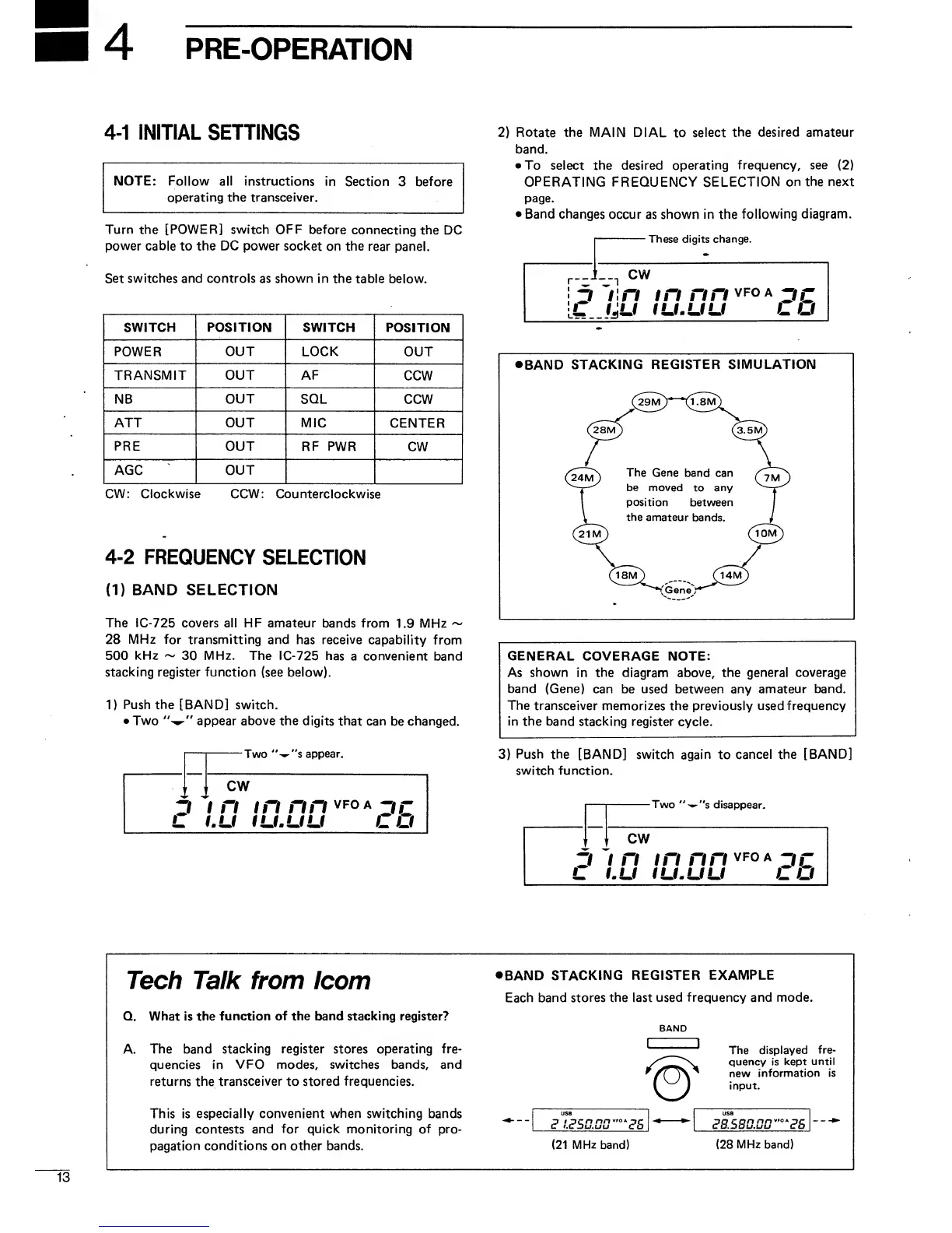
4-1
INITIAL
SETTINGS
NOTE: Follow all
instructions in
Section
3
before
operating
the
transceiver.
Turn the [POWER] switch OFF
before
connecting the
DC
power cable
to
the DC power
socket on the
rear panel.
Set
switches and controls as shown in
the table below.
SWITCH
POSITION
SWITCH POSITION
POWER OUT LOCK
OUT
TRANSMIT OUT
AF
CCW
NB
OUT
SQL
CCW
ATT OUT MIC
CENTER
PRE
OUT RF PWR
CW
AGC
OUT
CW: Clockwise
CCW: Counterclockwise
4-2
FREQUENCY
SELECTION
(1)
BAND
SELECTION
The IC-725 covers
all
HF
amateur
bands from
1.9
MHz
~
28
MHz
for transmitting and
has
receive
capability
from
500
kHz
~
30
MHz.
The IC-725
has
a
convenient
band
stacking register function
(see below).
1)
Push the
[BAND] switch.
•
Two
appear above the
digits that can
be
changed.
Two
^
s
appear.
r
1
CW
i n in nn
vfoa
oc
1.U
IU.UU
CO
2)
Rotate the MAIN
DIAL to
select
the desired amateur
band.
•
To
select the desired operating
frequency,
see
(2)
OPERATING FREQUENCY SELECTION
on
the next
page.
•
Band
changes
occur as shown in the
following
diagram.
These digits change.
n
CW
in
in
nn
vfoa
zic
IjU
IU.UU LU
BAND
STACKING
REGISTER SIMULATION
GENERAL
COVERAGE NOTE:
As shown
in
the diagram above, the general coverage
band (Gene)
can be used between any
amateur band.
The transceiver
memorizes the previously used frequency
in the band
stacking register cycle.
3)
Push
the [BAND] switch
again to
cancel the
[BAND]
switch function.
-Two
"^"s disappear.
CW
Zi
i n in nn
VF0A
zic
L
LU IU.UU
CO
Tech Talk from
Icom
Q.
What is the
function of the band stacking register?
A.
The band
stacking register stores operating fre-
quencies in
VFO modes, switches bands, and
returns
the
transceiver to stored frequencies.
This is
especially convenient when switching bands
during contests
and for
quick
monitoring of pro-
pagation
conditions on
other
bands.
BAND STACKING
REGISTER
EXAMPLE
Each
band stores
the
last
used frequency and mode.
BAND
c*
I.c?50.00
c*5
(21
MHz
band)
The displayed
fre-
quency is
kept
until
new
information is
input.
^8.580.00"
OA
^S
(28
MHz band)

 Loading...