2
INSTALLATION
2-1
UNPACKING
2-3
ANTENNA
After unpacking,
immediately describe any damage
to
the
delivering
carrier or dealer. Keep the shipping cartons. For
a
description and a diagram
of
accessory
equipment in-
cluded
with
the IC-725, see UNPACKING on the inside
front cover.
2-2
MOUNTING THE
TRANSCEIVER
Select
a
location
for the transceiver that allows adequate air
circulation and access to
the front and
rear panels. Do not
place in areas
subject
to
extr-eme heat, cold, or vibrations,
or near TV sets, radios
and electro-magnetic sources.
For mobile installations,
an
optional IC-MB5 MOBILE
MOUNTING
BRACKET
is
available..
Select
a
location
which
can
support
the weight of the transceiver and does
not interfere
with the
operation of the vehicle.
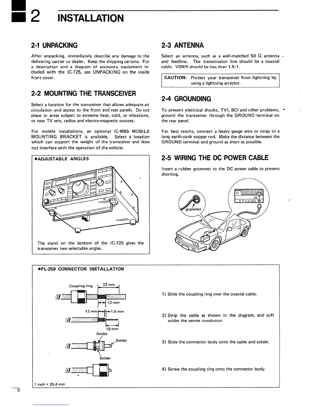
•ADJUSTABLE
ANGLES
The
stand
on the bottom
of the
IC-725
gives the
transceiver two
selectable
angles.
Select an antenna, such
as a
well-matched 50
12 antenna
and feedline.
The transmission
line
should be a
coaxial
cable. VSWR should
be less
than 1.5:1.
CAUTION:
Protect your
transceiver
from
lightning by
using
a
lightning arrestor.
2-4
GROUNDING
To
prevent
electrical shocks, TVI, BCI
and
other problems,
ground the
transceiver through
the GROUND
terminal on
the
rear panel.
For best results, connect
a
heavy
gauge wire or
strap to a
long earth-sunk
copper rod. Make the
distance
between the
GROUND terminal
and
ground
as
short as
possible.
2-5
WIRING THE
DC
POWER
CABLE
Insert
a
rubber grommet
to
the DC
power cable to
prevent
shorting.
PL-259
CONNECTOR INSTALLATION
Solder
1
)
Slide
the
coupling
ring over the
coaxial cable.
2)
Strip the cable as
shown in the
diagram, and
soft
solder the center conductor.
3)
Slide
the connector body onto the cable and solder.
4)
Screw the coupling
ring onto
the connector
body.
1
inch
=
25.4
mm

 Loading...