MAINTENANCE AND
ADJUSTMENT
g
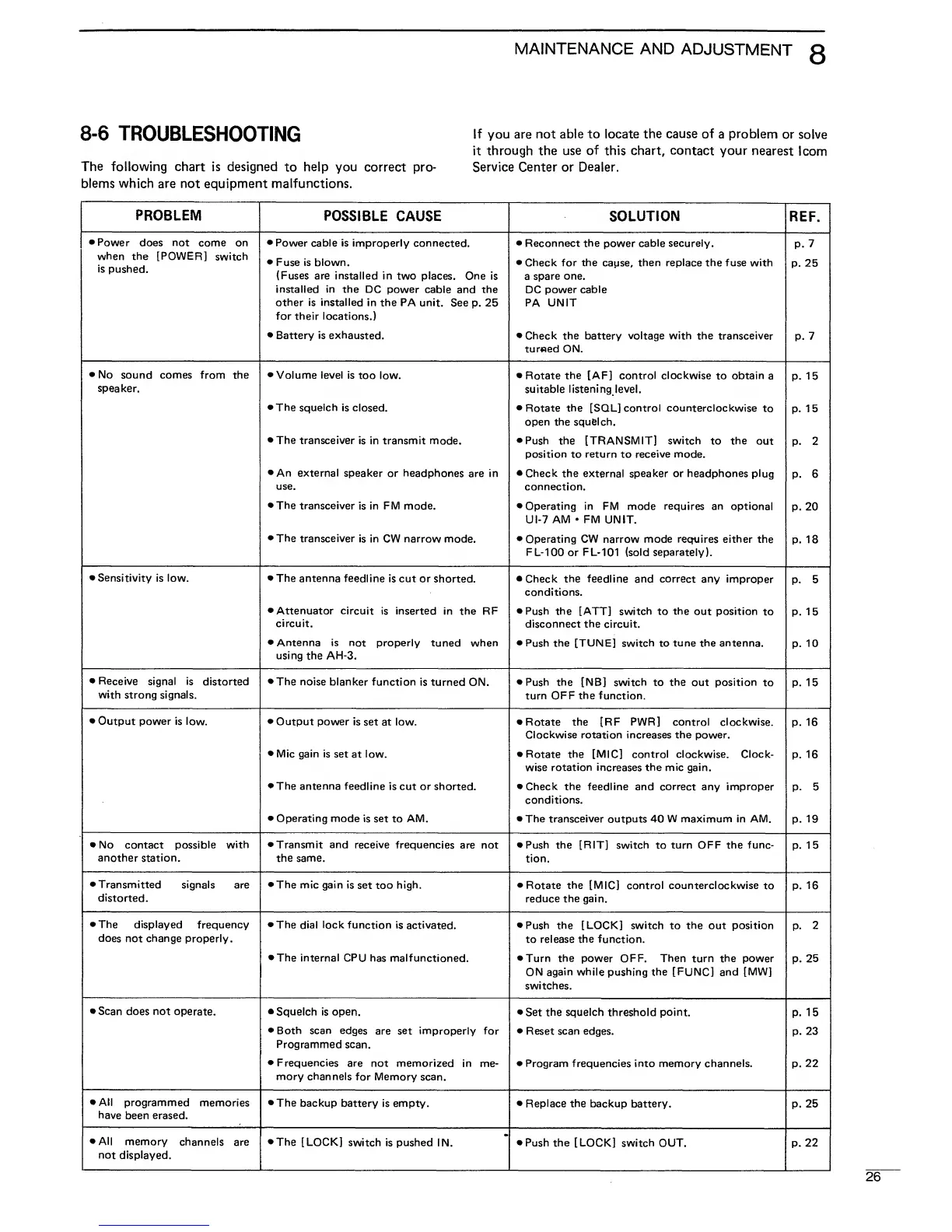
8-6
TROUBLESHOOTING
lf
y°
u are not
ab,e to locate the cause of
a
problem
or solve
it
through the use
of
this chart, contact your
nearest
I com
The
following chart
is
designed
to
help you
correct pro- Service Center or
Dealer,
blems which are not equipment malfunctions.
PROBLEM
POSSIBLE
CAUSE SOLUTION
REF.
•
Power
does
not
come on
when the [POWER]
switch
is
pushed.
•
Power
cable is improperly
connected.
•
Fuse is blown.
(Fuses
are installed in
two
places.
One is
installed
in
the DC power
cable and the
other is installed
in the PA unit.
See
p.
25
for their locations.)
•
Battery
is
exhausted.
•
Reconnect the
power
cable securely.
•
Check for the
cause,
then replace the fuse with
a
spare one.
DC
power cable
PA UNIT
•
Check the battery voltage with the transceiver
turned ON.
P.
7
p.
25
P.
7
•
No
sound comes from the
speaker.
•
Volume
level
is
too low.
•
The squelch
is
closed.
•
The
transceiver is
in
transmit
mode.
•
An external
speaker or headphones
are in
use.
• T*hp "trsin^ppiv/Pr ic in
FIV/I
mnrip
w
1
IIC
11 Ol IOUCIVCI
15 III 1 IVI IMUUC.
•
The
transceiver
is in
CW
narrow
mode.
•
Rotate
the [AF] control clockwise
to
obtain
a
suitable
listening level.
•
Rotate
the
[SQL]
control counterclockwise
to
open
the squelch.
•
Push the [TRANSMIT] switch
to
the
out
position
to
return
to
receive mode.
•
Check the
external
speaker
or
headphones
plug
connection.
A finorotinn in PIV/I mnHo rQfit livoc sin nn+i^nal
m
Upcrdlliiy 111
r
IVI
(TlUUc
icl^UIICb dil
UpilUflal
UI-7
AM
•
FM
UNIT.
•
Operating
CW
narrow
mode
requires
either
the
FL-100
or
FL-101 (sold separately).
p.
15
p.
15
P.
2
p.
6
p.
ZU
p.
18
•
Sensitivity
is low.
•
The
antenna feedline
is cut or
shorted.
•
Attenuator
circuit is inserted
in the RF
circuit.
•
Antenna is
not properly tuned when
using
the
AH-3.
•
Check
the
feedline and correct any
improper
conditions.
•
Push the [ATT]
switch to
the
out position
to
disconnect
the
circuit.
•
Push the [TUNE] switch to
tune
the antenna.
p.
5
p.
15
p.
10
•
Receive signal is
distorted
with
strong
signals.
•
The noise
blanker function
is turned
ON.
•
Push the [NB]
switch to
the
out
position
to
turn OFF
the
function.
p.
15
•
Output power is
low.
•
Output power is
set at low.
•
Mic gain is
set
at
low.
•
The antenna
feedline
is cut
or
shorted.
•
Operating mode
is set
to
AM.
•
Rotate
the
[RF
PWR]
control clockwise.
Clockwise rotation increases the power.
•
Rotate the [MIC] control clockwise. Clock-
wise
rotation
increases
the mic
gain.
•
Check the
feedline and correct any improper
conditions.
•
The transceiver outputs 40 W maximum in AM.
p.
16
p.
16
p.
5
p.
19
•
No
contact
possible
with
another
station.
•
Transmit and
receive frequencies
are not
the same.
•
Push the
[RIT]
switch
to
turn OFF the
func-
tion.
p.
15
•
Transmitted signals
are
distorted.
•
The
mic gain is
set too
high.
•
Rotate
the
[MIC] control counterclockwise
to
reduce the gain.
p.
16
•
The displayed
frequency
does not
change
properly.
•
The
dial lock function
is
activated.
•
The internal
CPU has malfunctioned.
• Push thp N OPKl cwitrh tn thp nut nnsitirm
to release
the
function.
•
Turn the
power OFF.
Then
turn the power
ON
again while pushing the
IFUNCJ
and
IMWJ
switches.
n 9
p.
z
p.
25
•
Scan
does
not
operate.
•
Squelch is open.
•
Both scan
edges
are
set improperly for
Programmed scan.
•
Frequencies
are
not memorized in
me-
mory channels
for Memory scan.
•
Set the squelch threshold point.
•
Reset scan edges.
•
Program frequencies
into
memory channels.
p.
15
p.
23
p.
22
•
All
programmed
memories
have
been
erased.
•
The
backup battery
is empty.
•
Replace
the
backup battery.
p.
25
•
All
memory
channels are
not displayed.
•
The
[LOCK]
switch is pushed
IN.
•
Push the [LOCK]
switch OUT.
P-
22

 Loading...