3-10
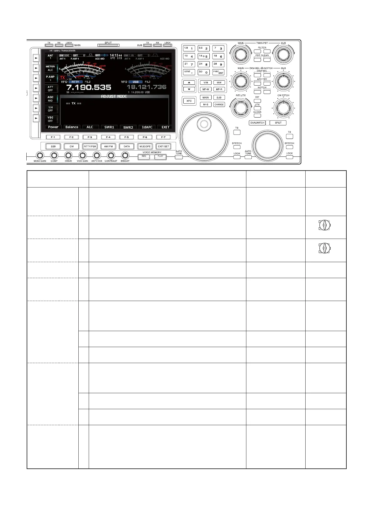
3-6 TX ADJUSTMENTS
• TX adjustment screen
RF-A UNIT
RF-A UNIT
MAIN UNIT
ADJUSTMENT OPERATION
ADJUSTMENT
ITEM/POINT
VALUE
-PREPARATION- 1 1) Connect an RF power meter to the [ANT1] connector.
2) Push [F-4] (TX) to enter the TX adjustment menu.
3) Push [F-1] (Power).
• “POWER HF PRESET” is displayed.
–
Push [F-4].
[ POWER HF PRE-
SET]
2 1) Set R983 (MAIN UNIT) to the center position.
2) Push [F-7].
• “POWER 50M PRESET” is displayed.
R983
(MAIN UNIT)
Center
osition
[ POWER 50M
PRESET]
3 1) Set R985 (MAIN UNIT) to the center position.
2) Push [F-7].
• “TX POWER SET” is displayed.
R985
(MAIN UNIT)
Center
osition
4 • Push [F-7].
• “TX PEAK SET” is displayed.
[TX POWER SET]
Push [F-7].
[TX PEAK SET] 5 1) Trim the coils and capacitor to adjust the TX output power.
2) Push [F-7].
• “Residual AM” is displayed.
L1071, C1102, L1112
(MAIN UNIT)
(Repeatedly)
Maximum TX
output power
[RESIDUAL AM] 6•
Connect an Audio Generator to the MIC input [MIC], and then
set it as:
• Frequency: 1.0 kHz
• Level: 10 mVrms
– –
7• Rotate C1102 to adjust the TX output power. C1102
(MAIN UNIT)
Maximum TX
output power
8 • Push [F-7].
• “TX Total Gain” is displayed.
–
Push [F-7].
[TX TOTAL GAIN] 9• Connect an Audio Generator to the MIC input [MIC], and
then set it as:
• Frequency: 1.5 kHz
• Level: 10 mVrms
– –
10 • Rotate R1074 to adjust the TX output power. R1074
(MAIN UNIT)
100 W
11 • Push [F-7].
• “POWER HF 0W” is displayed.
–
Push [F-7].
TX POWER SET
(HF)
-PREPARATION-
12 1) Connect an Audio Generator to the MIC input [MIC], and
then set it as:
• Frequency: 1.5 kHz
• Level: 10 mVrms
2) Push [F-7].
• “POWER HF 5W” is displayed.
[POWER HF/50M 0W]
–

 Loading...