4 - 6
LINE NAME DESCRIPTION
IN/
OUT
STATUS CONDITION
MMUTE MIC mute SW (Q51) control signal. OUT Low While TX AF line is mute.
SEG1–
SEG34
LCD (DS1) segments. OUT – –
COM1–
COM4
LCD (DS1) common terminal. OUT – –
LINE NAME DESCRIPTION
T1
BPF tuning volatages.
T2
T3
T4
MODMAX Maximum deviation adjust voltage.
MOD30 30% deviation adjust voltage.
VOL RX audio level adjust avoltage.
REFV Reference frequency adjustment voltage.
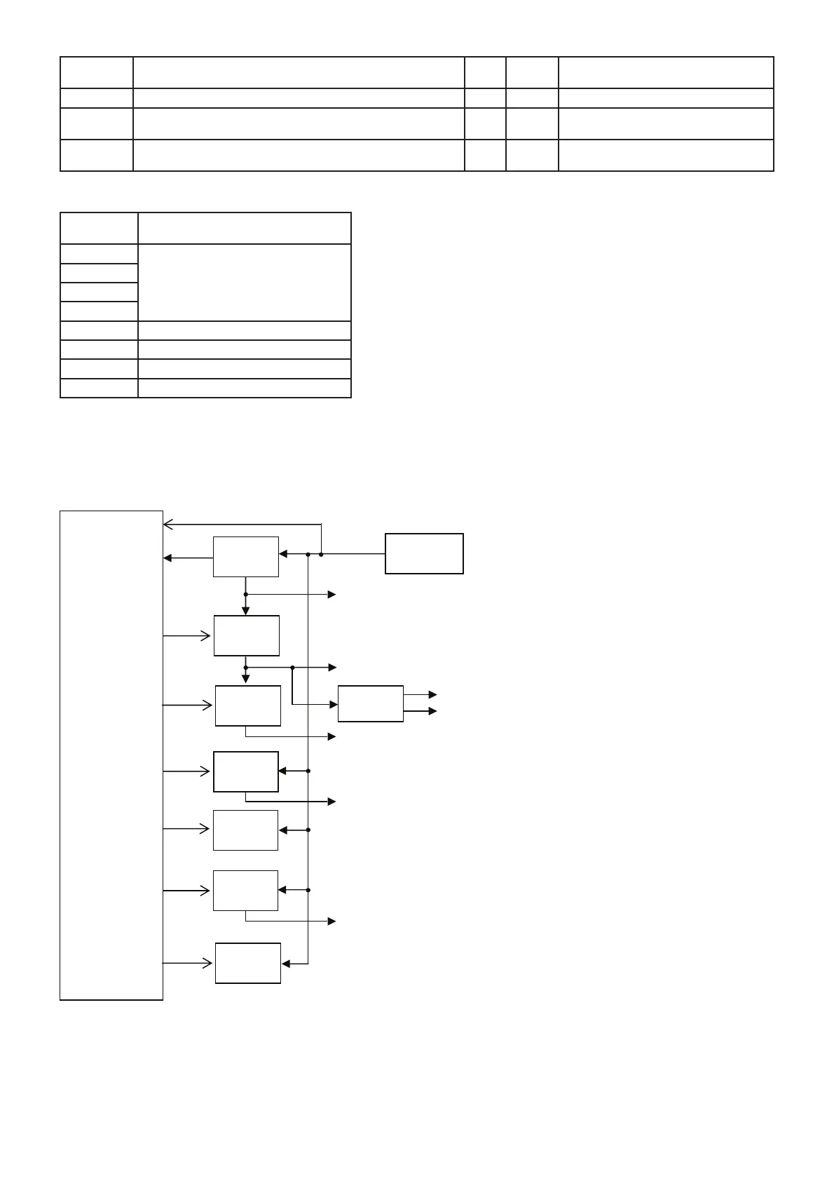
• DAC (IC17)
• CPU (IC26) (continued)
CPU3.6V
Regulator
Battery pack
R5S
SW
CPU
(IC26)
+5V
Regulator
VCO
SW
TX VCO (Q59, D45, 46)
VIN
VCC
IC22
Q70, 71
Q20, 90
Q57
Q25, 26
Q75, 76
Q7, 8
CPU3.6V
PCON
R5C
AF PWR AMP
Controller
AFC
TXV
Regulator
TXC
Backlight
driver
EXT
Regulator
EXTREG
LIGHTC
Common 5V: PLL IC (IC29), Reference oscillator (X5), Noise AMP (IC28), etc
RX 5V: IF IC (IC1), RF AMP (Q11), 1st IF AMP (O13), etc.
RX VCO (Q58, D38, 48)
Logic 3.6V: EEPROM (IC25), Reset IC (IC24),etc.
External 5V: Connected microphone.
TX 5V: Pre-driver (PA: Q4), APC AMP (PA: IC27), etc.
4-5 VOLTAGE BLOCK DIAGRAM
Voltage from the attached battery pack is routed to the whole of the transceiver via regulators and switches.
 Loading...