4 - 1
SECTION 4 CIRCUIT DESCRIPTION
4-1 RECEIVER CIRCUITS
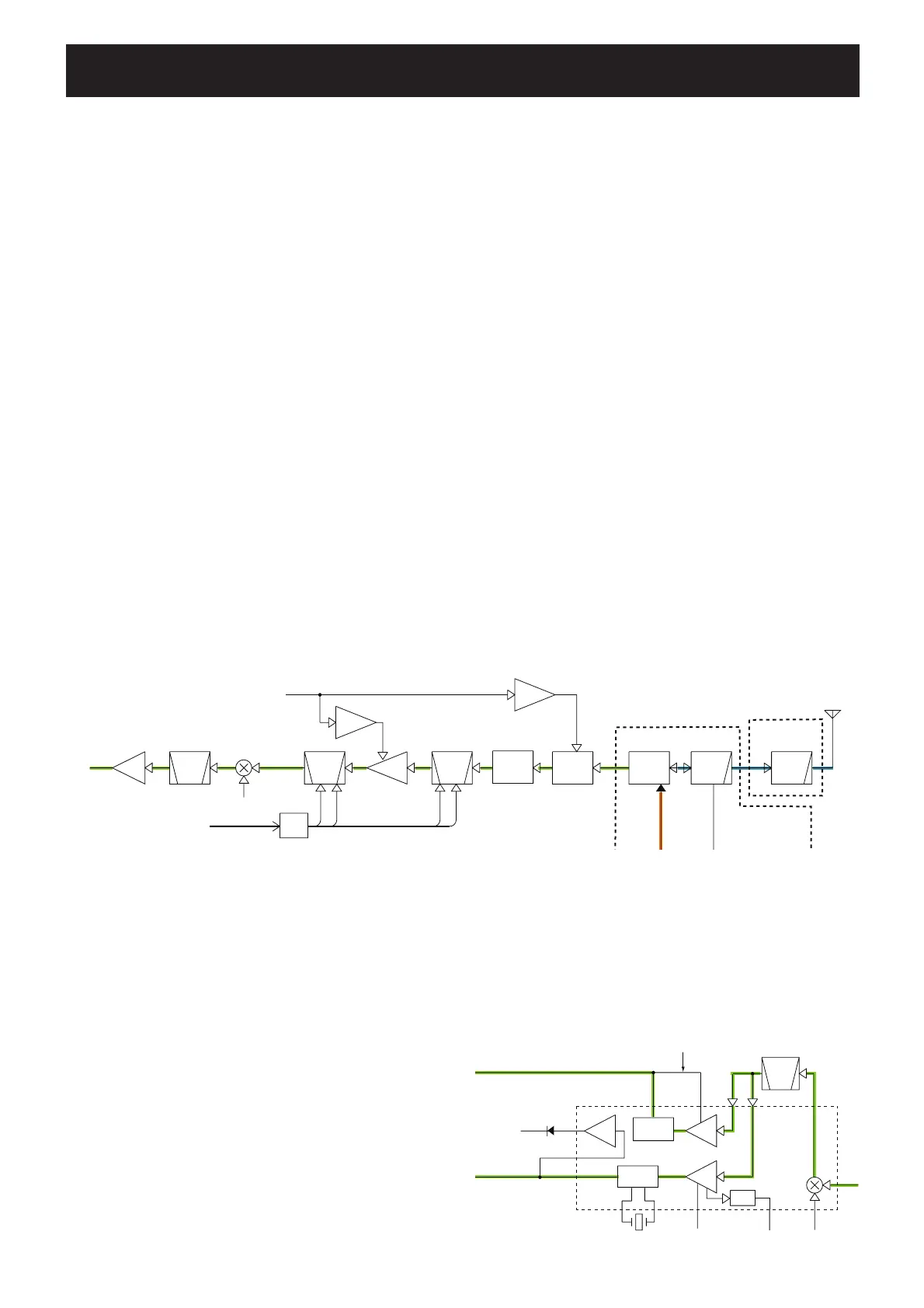
RF CIRCUITS
RF circuits consist of RF fi lters, antenna switch (ANT SW),
RF amplifi er (RF AMP), etc., and extracts and amplifi es the
signals of frequency which desired to receive.
The received signals (RX signals) from the antenna are
entered to the ANT UNIT and passed through the LPF. The
fi ltered RX signals are entered to the PA UNIT, and passed
through the LPF and ANT SW (an LPF in RX), then entered
to the MAIN UNIT.
The RX signals from the PA UNIT are passed through the
attenuator (ATT), BEF and 2-staged tuned BPF, then applied
to the RF AMP (Q11). The amplifi ed RX signals are passed
through another 2-staged tuned BPF, and applied to the 1st
mixer (Q12).
The ANT SW toggles RX line and TX line. While receiving,
the TX line and the antenna is disconnected to prevent RX
signals entering. The RX line is disconnected from the GND
simultaneously, and an LPF which guides received signals
to the RX circuits is composed.
While transmitting, serial-connected PIN diodes are ON,
thus the TX line is connected to the antenna, and the RX
line is connected to the GND simultaneously to prevent
transmit signal entering.
The ATT functions as a part of the AGC circuit. The AGC
voltage which is applied to the PIN diodes of the ATT
controls RX signal level to enter the RX circuits, to keep the
demodulated AF signal level stable.
The tuned-BPF is adjusted so that it responds to receiving
frequency and rejects all others, by the variable capacitor
whose capacitance is varied by applied tuning voltages; "T1
–T4."
The RF AMP amplifi es RX signals to a level suited to the 1st
mixer.
1ST IF CIRCUITS
The 1st IF circuits consist of 1st mixer, 1st IF fi lter and 1st
IF amplifier. And it converts the RX signals into the 1st IF
signal, then fi lters to remove unwanted signals and amplifi es.
The filtered RX signals are applied to the 1st mixer to be
converted into the 46.35 MHz 1st IF signal, by being mixed
with the 1st Local Oscillator (LO) signals from the RX VCO
via buffers (Q60 and Q28), LO SW (D17) and ATT (R63,
335, 336).
The converted 1st IF signal is passed through the 1st IF fi lter
(FI3) to be removed unwanted signals, and amplifi ed by the
1st IF AMP (Q13). The amplifi ed 1st IF signal is then applied
to the 2nd IF circuit.
• RF AND 1ST IF CIRCUITS
• 2ND IF CIRCUIT
2ND IF AND DEMODULATOR CIRCUITS
The 2nd IF circuit consists of 2nd mixer, 2nd IF filter, 2nd
IF amplifier. And it converts the 1st IF signal into the 2nd IF
signal, then filters and amplifi es 2nd IF signal only. And the
demodulator circuit converts the 2nd IF signal to AF signals.
IC1 is an IF IC which contains the whole of the 2nd IF
and demodulator circuits for the both of AM and FM
demodulation.
The amplified 1st IF signal from the 1st IF AMP is applied
to the IF IC, and converted into the 2nd IF signal, by being
mixed with the 45.9 MHz 2nd LO signal at internal 2nd
mixer.
The 2nd LO signal is generated by PLL IC (IC29) and X5,
and tripled by Q84 before being applied to the 2nd mixer.
• AM signals
The converted 2nd IF signal is filtered by external 2nd IF
filter (FI2), and amplified by the internal 2nd IF AMP. The
amplified 2nd IF signal is AM-demodulated by internal AM
detector, then output from pin 14.
The demodulated AF signals are applied to the RX AF
circuits via the ANL (Automatic Noise Limiter) circuit which
reduces pulse-type noises, if the ANL function is activated.
• FM (Weather Alert) signals
The converted 2nd IF signal is filtered by external 2nd
IF filter (FI2), and amplified by internal 2nd IF AMP. The
amplified 2nd IF signal is FM-demodulated by quadrature
detector, then output from pin 11.
The demodulated AF signals are applied to the RX AF
circuits.
ANTENN
LPF
ANT
SW
BPF
RF
AMP
BPF
BPF
XTALIF
AMP
AGC
AM P
AGC
AM P
ATT
T4
T3
T1
T2
46.350MHz
D1,D8
D75
BEF
L52,C235
Q80
D13,50
Q10
Q11
D14,D15
L21,22
C67,71,73,326
Q12
1st IF FILTER
1st MIXER
1st IF AMP
Q13
IC17
DAC
SCK,SDATA
DA2STB
FI3
RF AGC
RF AGC from IF IC
1st LO signal
PA UNIT
MAIN UNIT
LPF
L1,45
C210-212
L3
C5-7
L18,69,
C60,327,780,781
ANT UNIT
BPF
CERAMIC
FM
DET
AM
DET
X4
(Discriminator)
NOISE
450kHz
2nd IF
2nd IF FILTER
2nd MIXER
IC1
IF IC
FI2
DET
AM DET
AGC feedback
20
11617
10
11
12
13
14 18
57
3
FM DET
RSSI
RF AGC
45.9MHz 2nd LO
(AM)
(FM)
2nd
IF
2nd
IF
OP.
AMP
RSSI