3 - 1
SECTION 3 DISASSEMBLY INSTRUCTION
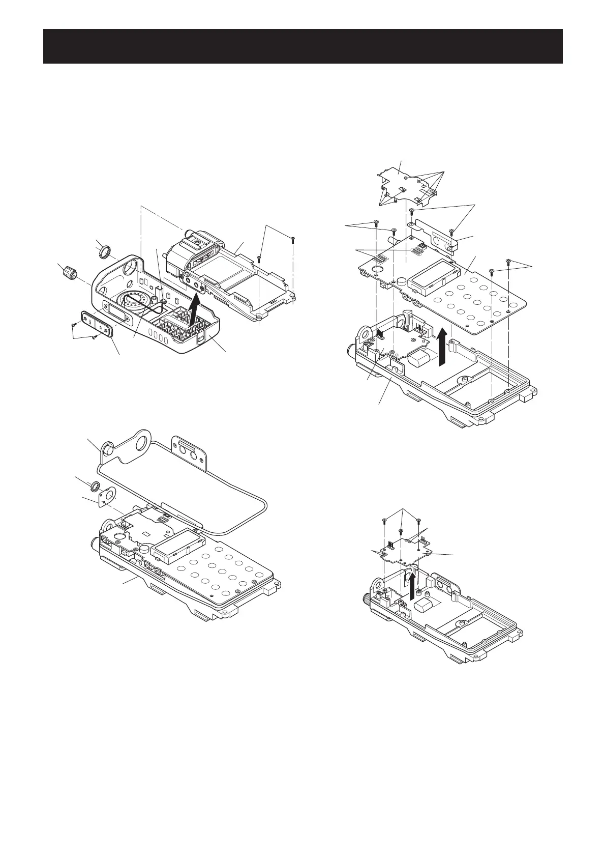
1. Removing the front panel
q Remove the VR knob and antenna nut.
w Unscrew 2 screws from the bottom.
e Unscrew 2 screws from the side, and remove the jack
panel.
r Take off the CHASSIS assembly in direction of the arrow
until the speaker cable appears.
t Disconnect the speaker connector from the CHASSIS
assembly, and separate the front panel and CHASSIS
assembly completely.
w Unsolder total of 8 points from the shield cover then
remove it.
e Unscrew 2 screws from the side plate then remove it.
r Unscrew total of 4 screws from the MAIN UNIT.
t Unsolder total of 12 points which connecting PA UNIT,
then remove the MAIN UNIT from the CHASSIS.
2. Removing the MAIN UNIT
q
Remove the seal, VR nut and VR plate from the CHASSIS
assembly.
Chassis
assembly
2 screws
Speaker
connector
Speaker
cable
Jack
anel
Antenna nut
VR knob
Front panel
Seal
VR nut
VR plate
Chassis
assembly
Shied cover
MAIN UNIT
PA UNIT
12 points
2 screws
2 screws
2 screws
4 points
4 points
Side plate
Chassis
PA UNIT
2 points
2 points
3 screws
3. Removing the PA UNIT
q Unscrew 3 screws from the PA UNIT.
w Unsolder total of 4 points then remove the PA UNIT from
the CHASSIS.
(Continued to right above)
 Loading...