4 - 3
4-2 TRANSMITTER CIRCUITS
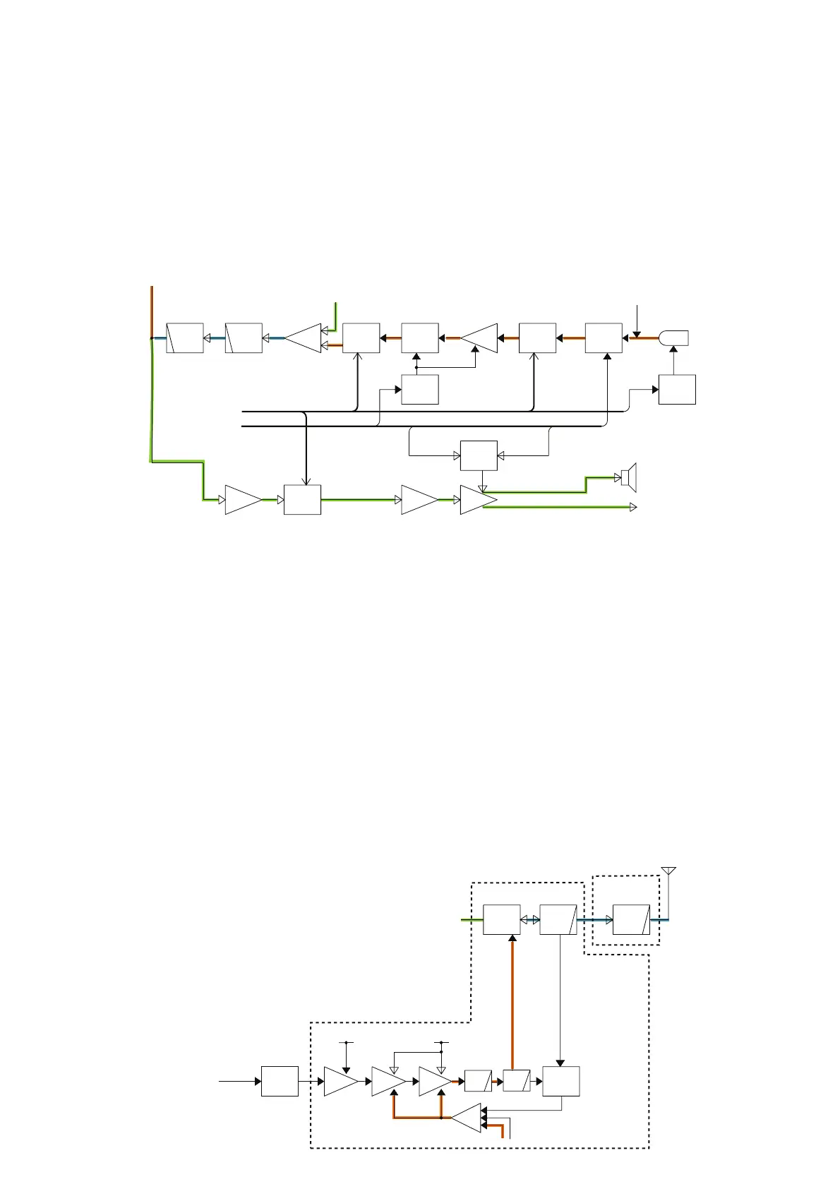
TX AF CIRCUITS
The TX AF circuit consists of microphone amplifier (MIC
AMP), ALC and AF fi lters. ALC (Automatic Level Control) is
an amplifi er which reduces its gain automatically to prevent
over deviation.
The audio signals from the connected headset's microphone
(MIC signals) are passed through the MIC mute SW (Q51)
and the DAC (IC17_6) which adjusts the MIC signal level.
The level-adjusted MIC signals are amplified by the MIC
AMP (Q86), then applied to the ALC AMP (IC15).
The ALC (Automatic Level Control) AMP is an amplifier
which controls its gain automatically according to the MIC
signals level. The ALC provides stable modulation signals
by limiting the amplitude of MIC signals to prevent the over
deviation.
The output signals of ALC are applied to another DAC
(IC17_5) for level (deviation) adjustment. The level-adjusted
MIC signals are passed through the buffer (IC18a) and
5-pole LPF (IC18b/c) to filter audio band signals only. The
filtered MIC signals are entered to the PA UNIT, and applied
to the APC AMP (PA: IC27) as the modulation signals.
APC CIRCUIT (PA UNIT)
The APC (Automatic Power Control) circuit stabilizes transmit
output power to prevent transmit output power level change,
which is caused by load mismatching or heat effect, etc.
The power detector rectifi es a portion of the TX signal and
converts it into DC voltage which is in proportion to the
transmit output power level. The detected voltage is applied
to the input terminal (pin 3) of APC AMP (IC27; as a com-
parator). The TX power setting voltage “POW” is applied to
another input terminal (pin 1) as the reference voltage.
The comparator compares the detected voltage and refer-
ence voltage, and the difference of voltage is output from
output terminal. The output voltage controls the bias of the
driver and power amplifiers to reduce/increase the gain of
these amplifi ers for stable TX output power.
ANTENN
LPF
ANT
SW
PWR
AMP
DRIVE
PRE
BPF
RF
AMP
AGC
MP
AM P
ATT
LPF
LPF
APC
AMP
DRIVE
AM P
T1
T2
POWER
DET
Q2
Q3
Q4
IC27
D2,D3,D74
D1,D8
D75
BEF
L52,C235
D13,50
Q10
Q11
,326
R36-38
HVTXV
MOD
4
3
1
1
PCON
ATT
signal
D75,D76,D77
PA UNIT
MAIN UNIT
LPF
L1,45
C210-212
L3
C5-7
L5
C12,14
L6,46
C19,212,297,
791,792,797
L18,69,
C60,327,780,781
ANT UNIT
MIC
MUT E
PWR
AMP
BUFF
LPFLPF
BUFF
From the ext. microphone
From the AM/FM SW (IC2)
MIC
AM P
PRE
AMP
To the ext. speaker
MMUT E
EMBI
ALCC
AFC
SPCON
MIC
CONTROL
AF AMP
CONTROL
ALC
CONTROL
To the int. speaker
(MIC VR)
DAC
IC17 _6
IC17 _5
IC17 _7
Q51
Microphone
MC1
D67
Q79
Q86
IC15
Q52
Q82,Q83,Q36
IC31
IC18a
IC18bIC18c
Control lines
from the CPU (IC26)
IC18d
DA2STB
SCK,SDATA
DA2STB
SCK,SDATA
DA2STB
SCK,SDATA
ALC
AM P
IC20
(MIC VR)
DAC
(VOLUME)
DAC
AM MODULATION CIRCUITS
The AM modulation circuits mudulate the carrier with the
MIC signals (=modulation signals).
The level-adjusted modulation signals from the MAIN UNIT
are applied to the APC AMP. The output voltege of APC
AMP which controls the gain of drive (Q3) and power (Q2)
AMPs swings corresponding to the amplitude of modulation
signals, thus the AM modulation is obtained.
TX AMPLIFIERS
The TX amplifers consist pre-driver, driver and power
amplifi ers, and amplify the VCO output to the transmit output
level.
The TX VCO (Q59, D45, 46) output is applied to the pre-
driver
via buffers (Q60 and Q28), LO switch (D6) and ATT,
and amplified by the pre-driver (Q4) to the driver (Q3) input
level. The amplified TX signal is amplified by driver (Q3) to
the power AMP (Q2) input level, then power-amplified by the
power AMP (Q2) to the TX output level.
The power-amplified TX signal is passed through the LPF,
ANT SW and LPF and entered to the ANT UNIT, then
applied to the antenna via the LPF
.
• AF CIRCUITS (for RX and TX)
• AM MODULATION, TX AMPLIFIERS AND APC CIRCUITS
 Loading...