CIRCUIT DESCRIPTION
5-1 RECEIVER CIRCUITS
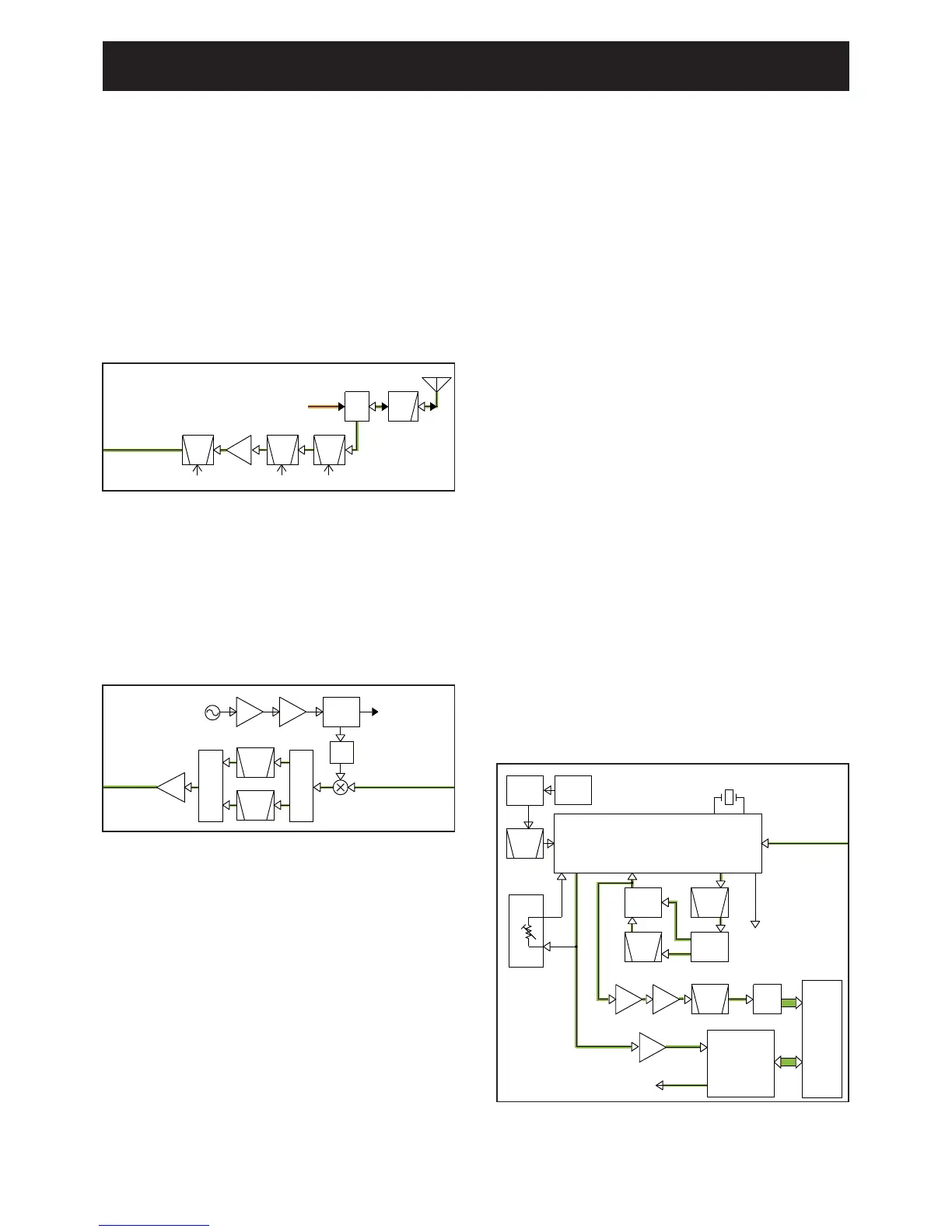
RF CIRCUITS
The RX signal from the antenna is passed through the LPF
and antenna SW (D24–D26, D28, D32), then fi ltered by the
2-staged tuned BPFs (D31 and D37) to eliminate unwanted
out-of-band signals. The fi ltered RX signal is amplifi ed by the
RF AMP (Q20), and fi ltered by another tuned BPF (D21) to
obtain a good image response, then applied to the 1st IF cir-
cuits.
The BPFs are tuned to the RX frequency by applying ad-
equate tuning voltages: “T1” and “T2” to the variable capaci-
tors.
• RF CIRCUITS
1ST IF CIRCUITS
The RX signal from the RF circuits is applied to the 1st IF
mixer (Q19) and mixed with the 1st LO signal from the RX
VCO, resulting in the 46.35 MHz 1st IF signal. The 1st IF
signal is passed through the IF SWs (D13, D14, D17, D18)
and the crystal fi lter (FI4: analog mode, FI5: digital mode) to
be fi ltered, amplifi ed by the 1st IF AMP (Q14), then applied
to the 2nd IF circuits.
• 1ST IF CIRCUITS
2ND IF AND DEMODULATOR CIRCUITS
The signal from the 1st IF circuits is applied to the IF demod-
ulator IC (IC4) which contains the 2nd IF mixer, 2nd IF AMP,
FM detector, squelch circuit and AF AMP in its package.
The 1st IF signal is applied to the 2nd IF mixer and mixed
with the 2nd LO signal resulting in the 450 kHz 2nd IF signal.
The 2nd LO signal is generated by tripling the 15.3 MHz
reference frequency signal generated by the reference fre-
quency oscillator (TCXO; X2).
• WHILE OPERATING IN THE ANALOG MODE
The 2nd IF signal is filtered by the 2nd IF filter (FI2: wide/
middle mode) or fi lters (FI1 and FI2: narrow) to eliminate un-
wanted signals. It is amplifi ed by the 2nd IF AMP, and then
demodulated by the detector circuit, which employs the dis-
criminator (X1) as the phase shifter.
The demodulated AF signal is amplified by the AF AMP
(IC6), and then applied to the linear codec (IC2006). The AF
signal is converted into a digital audio signal by the linear
codec (IC2006), processed by the DSP (IC2007), and then
decoded into an analog audio signal.
• WHILE OPERATING IN THE DIGITAL MODE
The 2nd IF signal is fi ltered by the 2nd IF fi lters (FI1 and FI2)
to eliminate unwanted signals, and applied to the IF AMP
(IC5) through the buffer (Q5). The amplifi ed 2nd IF signal is
passed through the ceramic fi lter (FI3), and then applied to
the A/D converter (IC2002) to be encoded into a digital sig-
nal. The digital signal is demodulated by the DSP (IC2007),
and then applied to the linear codec (IC2006) to be decoded
into an analog audio signal.
The AF signal is applied to the RX AF circuits.
• 2ND IF AND DEMODULATOR CIRCUITS
LPF
ANT
SW
D24-D26,
D28,D32
RF
AMP
Q20
BPF
D21 D37
BPF
T2
T1
D31
BPF
T1
From the TX circuits
To the 1st IF circuits
ANT
LO
SW
D5,D6
D17,D18D13,D14
Q19
BPF
XTAL
FI4
IF
AMP
Q14
BUFF
Q8
BUFF
Q10
ATT
IF SW
IF SW
RX VCO
To the TX circuits
From the RF circuits
 Loading...