EasyManuals Logo
Home>Icom>Transceiver>IC-F5123D

Icom IC-F5123D Service Manual

Icom IC-F5123D
40 pages
To Next Page IconTo Next Page
To Previous Page IconTo Previous Page
Page #9 background imageLoading...
Page #9 background image
3 - 1
SECTION 3
.
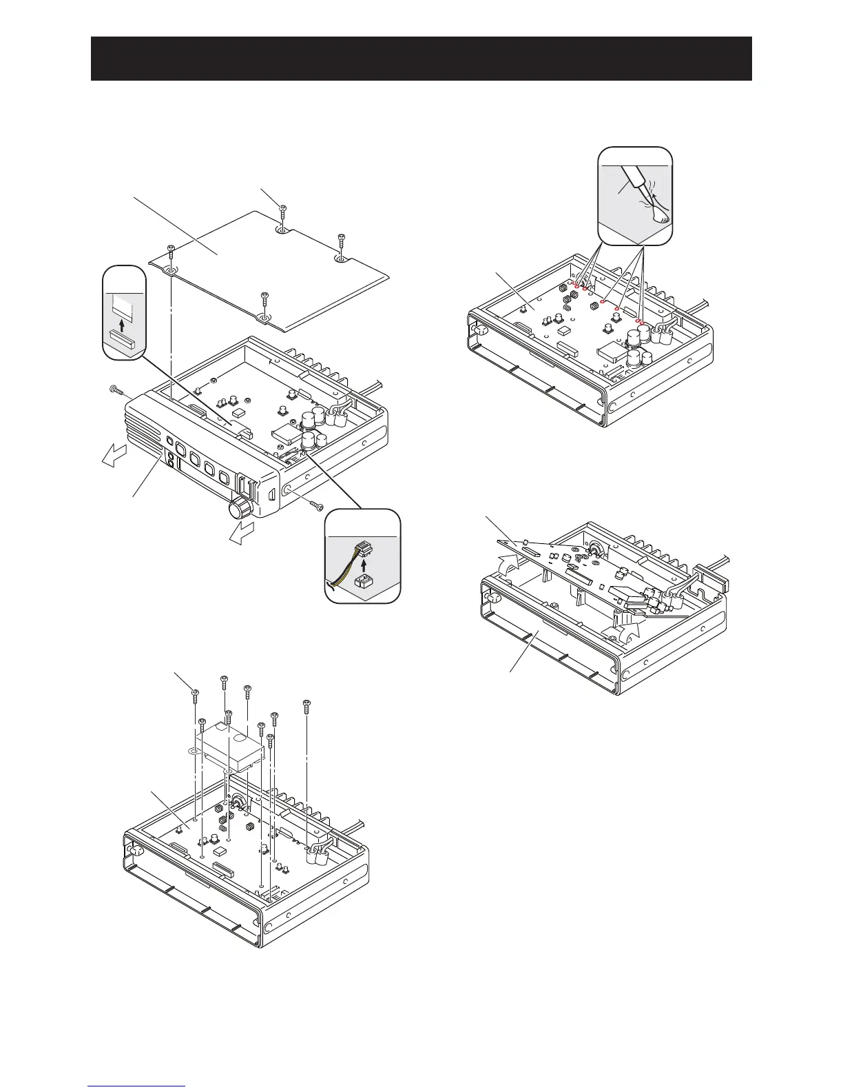
DISASSEMBLY INSTRUCTION
FLAT
CABLE
BOTTOM COVER
SCREW×4
FRONT PANEL
SPEAKER
CABLE
UNSOLDER
Solder
remover
MAIN UNIT
MAIN UNIT
CHASSIS
MAIN UNIT
SCREW×9
1) Remove 4 screws from the bottom cover, and then
remove it.
2) Disconnect the fl at cable and speaker cable.
3) Remove 2 screws from the both sides of the front panel,
and then remove it in the direction of the arrow.
4) Remove 9 screws from the MAIN UNIT.
5) Unsolder total of 7 points; 3 points at the antenna
connector, 4 points at the PA module.
6) Remove the MAIN UNIT from the CHASSIS in the
direction of the arrow.

Other manuals for Icom IC-F5123D

Questions and Answers:

Question and Answer IconNeed help?

Do you have a question about the Icom IC-F5123D and is the answer not in the manual?

Icom IC-F5123D Specifications

General IconGeneral
BrandIcom
ModelIC-F5123D
CategoryTransceiver
LanguageEnglish

Related product manuals