6 - 5
No over or under shoot.
As flat as possible.
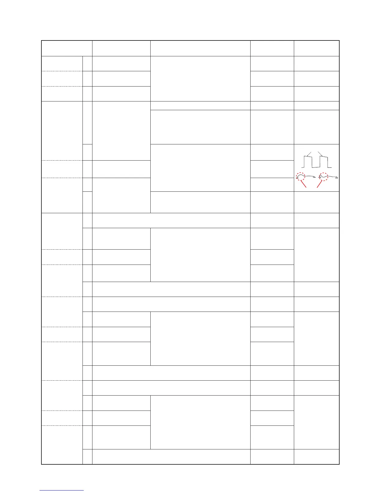
ADJUSTMENT
TRANSCEIVER’S
CONDITION
OPERATION
ADJUSTMENT
ITEM
VALUE
TX POWER
(Hi power)
1 • Channel : 1-6
• Transmitting
• Connect an RF power meter to the
antenna connector.
[Power (Hi)]
50 W [50 W ver.]
25 W [25 W ver.]
(L2 power) 2 • Channel : 1-7
• Transmitting
[Power (L2)]
25 W [50 W ver.]
10 W [25 W ver.]
(L1 power) 3 • Channel : 1-8
• Transmitting
[Power (L1)]
5.0 W [50 W ver.]
2.5 W [25 W ver.]
MODULATION
BALANCE
(Band low)
1 Channel : 1-9
• Transmitting
• Set the preset value.
[MOD (WIDE)] 150
1) Set the TX mode to "2" on the "Adjust
Utility" screen.
2) Push [ENTER] on the PC’s keyboard,
to enter the modulation balance
adjustment mode.
[BAL Start] –
2• Connect a modulation analyzer with an
oscilloscope to the antenna connector
through an attenuator, and set it as;
HPF : OFF
LPF : 20 kHz
De-emphasis : OFF
Detector : (P–P)/2
[BAL 1]
(Band center)
3 • Channel : 1-10
• Transmitting.
[BAL 2]
(Band high)
4 • Channel : 1-11
• Transmitting.
[BAL 3]
5• Push [ENTER] on the PC’s keyboard, to
store the value and quit the modulation
balance adjustment mode.
[BAL Start] –
FM DEVIATION
( Narrow mode)
-Band low-
1• Push [ENTER] on the PC’s keyboard, to enter the FM deviation
(For narrow mode) adjustment mode.
[MOD N Start] –
2 • Channel : 1-12
• Transmitting
• Connect a modulation analyzer to the
antenna connector through an attenuator,
and set it as described in the "MODULATION
BALANCE" above.
• Connect as audio generator to the [MIC]
jack, and set it as;
Frequency : 1 kHz (Sine wave)
Level : 40 mVrms
[MOD N L]
±2.05 to ±2.15
kHz
-Band center-
3 • Channel : 1-13
• Transmitting
[MOD N C]
-Band high-
4 • Channel : 1-14
• Transmitting
[MOD N H]
5• Push [ENTER] on the PC’s keyboard, to store the value and quit
the FM deviation (For narrow mode) adjustment mode.
[MOD N Start] –
(Wide mode)
-Band low-
6• Push [ENTER] on the PC’s keyboard, to enter the FM deviation
(For wide mode) adjustment mode.
[MOD W Start] –
7 • Channel : 1-15
• Transmitting
•
Connect a modulation analyzer to
the antenna connector through an
attenuator, and set it as described in the
"MODULATION BALANCE" above.
• Connect as audio generator to the [MIC]
jack, and set it as;
Frequency : 1 kHz (Sine wave)
Level : 40 mVrms
[MOD W L]
±4.05 to ±4.15
kHz
-Band center-
8 • Channel : 1-16
• Transmitting
[MOD W C]
-Band high-
9 • Channel : 1-17
• Transmitting
[MOD W H]
10 • Push [ENTER] on the PC’s keyboard, to store the value and quit
the FM deviation (For wide mode) adjustment mode.
[MOD W Start] –
(Middle mode)*
-Band low-
11 • Push [ENTER] on the PC’s keyboard, to enter the FM deviation
(For middle mode) adjustment mode.
[MOD M Start] –
12 • Channel : 1-18
• Transmitting
• Connect a modulation analyzer to the
antenna connector through an attenuator,
and set it as described in the "MODULATION
BALANCE" above.
• Connect as audio generator to the [MIC]
jack, and set it as;
Frequency : 1 kHz (Sine wave)
Level : 40 mVrms
[MOD M L]
±3.25 to ±3.35
kHz
-Band center-
13 • Channel : 1-19
• Transmitting
[MOD M C]
-Band high-
14 • Channel : 1-20
• Transmitting
[MOD M H]
15 • Push [ENTER] on the PC’s keyboard, to store the value and quit
the FM deviation (For middle mode) adjustment mode.
[MOD M Start] –
6-3 TRANSMIT ADJUSTMENTS
1) Select an adjustment item using [
↑
]/[
↓
] on the PC's keyboard.
2) Set or modify the adjustment value as specifi ed using [
←
]/[
→
] on the PC's keyboard, then push [ENTER].
*: [EUR] only
 Loading...