6-3 TRANSMIT ADJUSTMENT
1) Select an adjustment item using cursor or [
↑
] / [
↓
] keys of the PC’s keyboard.
2) Set or modify the adjustment value as specifi ed using [
←
] / [
→
] keys of the PC’s keyboard, then push the [ENTER] key.
ADJUSTMENT ADJUSTMENT CONDITION OPERATION
ADJUSTMENT
ITEM
VALUE
TX
Output Power
-Preparation-
1
–
• Connect an RF power meter to the
TX antenna connector.
––
-Adjust-
(Hi Power)
2 • CH. : 1-10
• Transmitting
1)
Adjust the TX output power using [
←
]
/ [
→
] keys of the PC’s keyboard.
2) Push the [ENTER] key to store the
adjust value.
[Power(Hi)]
50 W
[FR5000]
25 W
[FR5100]
(L2 Power) 3 • CH. : 1-11
• Transmitting
[Power(L2)]
25 W
[FR5000]
10 W
[FR5100]
(L1 Power) 4 • CH. : 1-12
• Transmitting
[Power(L1)]
5 W
[FR5000]
2.5 W
[FR5100]
MODULATION
BALANCE
-Preparation-
1• Connect a Modulation Analyzer
to the TX antenna connector
through an attenuator.
• Set the Modulation Analyzer as;
HPF : OFF
LPF : 20 kHz
De-emphasis : OFF
Detector : (P-P)/2
––
2 – • Set the item [TX Mode] to "2." [TX Mode]
"2"
-Adjust-
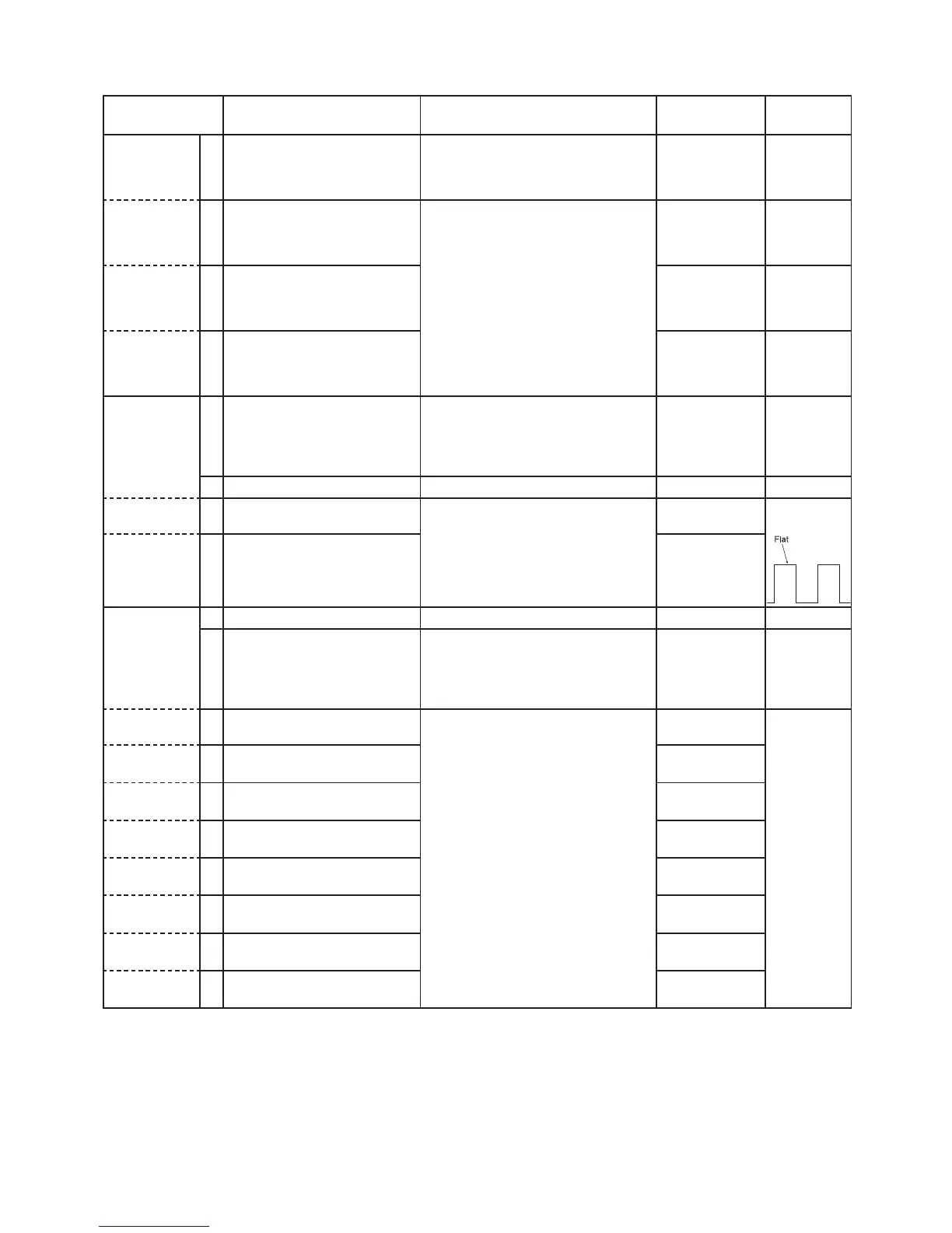
(TX VCO 1)
3 • CH. : 1-13
• Transmitting
1) Adjust the wave form using [
←
] / [
→
]
keys of the PC’s keyboard.
2) Push the [ENTER] key to store the
adjust value.
[BAL]
(square wave
form)
(TX VCO 2) 4 • CH. : 1-14
• Transmitting
[BAL Offset
(High]
DIGITAL
DEVIATION
-Preparation-
1 – • Set the item [TX Mode] to "16." [TX Mode]
"16"
2• Connect a Modulation Analyzer
to the TX antenna connector
through an attenuator.
• Set the Modulation Analyzer as;
HPF : OFF
LPF : 20 kHz
De-emphasis : OFF
Detector : (P-P)/2
––
-Adjust-
(Band 1)
3 • CH. : 1-15
• Transmitting
1) Adjust the deviation using [
←
] / [
→
]
keys of the PC’s keyboard.
2) Push the [ENTER] key to store the
adjust value.
[MOD (Digital)]
±1.39–1.43
kHz
(Band 2) 4 • CH. : 1-16
• Transmitting
[MOD Slant
Band 0]
(Band 3) 5 • CH. : 1-17
• Transmitting
[MOD Slant
Band 1]
(Band 4) 6 • CH. : 1-18
• Transmitting
[MOD Slant
Band 2]
(Band 5) 7 • CH. : 1-19
• Transmitting
[MOD Offset
(High)]
(Band 6) 8 • CH. : 1-20
• Transmitting
[MOD Slant
Band 3]
(Band 7) 9 • CH. : 1-21
• Transmitting
[MOD Slant
Band 4]
(Band 8) 10 • CH. : 1-22
• Transmitting
[MOD Slant
Band 5]
6 - 7
 Loading...


