3. Remove the transceiver case
as
shown on
Page
6 -
1.
Use
a screw driver
that
fits the screw.
4.
To open the hinge chassis remove
the
two screws
as
shown on
Page
6 - 2.
5. Attach an
8.0 ~ 11.0V
DC
external power source
to
the battery clip or screw.
Be
sure
to
check
the
polarity.
6.
In
the
case of a transmission problem, a dummy load should be connected
to
the
antenna connector.
In
the case
of
a receiving problem, an antenna or signal generator
is
connected
to
the
antenna
connector.
Be
careful not
to
transmit into the signal generator.
7.
Recheck for
the
suspected malfunction with the power switch on.
8. Check
the
defective circuit and measure the
DC
voltages of the collector, base and emitter of each
transistor.
9.
When
checking a transmission problem, it
is
convenient
to
short circuit an accessory mic connector
plug and insert it, turning on the transmitter.
7 - 4 HOW TO CHECK
7-4-1
RECEIVE
1. Check
the
frequency of P.L.L. unit when you are unable
to
receive with a strong signal present and
noise present when turning up the AF
volume.
2.
When
no noise
is
present
at
the speaker, check audio frequency amplifier or 6V regulator first.
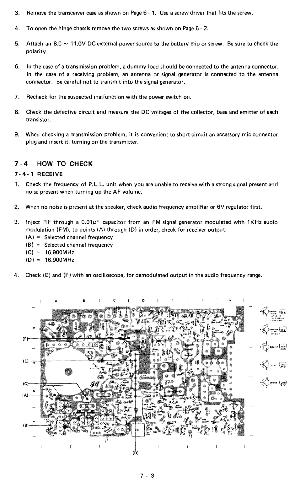
3.
Inject
RF
through a
O.OlµF
capacitor from an
FM
signal generator modulated with 1
KHz
audio
modulation (FM),
to
points
(A)
through
(D)
in
order, check for receiver output.
(A)
= Selected channel frequency
(B)
= Selected channel frequency
(C)
= 16.900MHz
(D)
= 16.900MHz
4. Check (E) and (F) with
an
oscilloscope, for demodulated
output
in
the
audio frequency range.
A
B
c D
(0)
7-3
E
F
G
,lv'\_,,,r:::-:i
~)mm
illl.1
t
1:tt-31H
 Loading...