5 - 3
ADJUSTMENT
ADJUSTMENT
ITEM
TRANSCEIVER’S
CONDITION
OPERATION VALUE
PLL LOCK
VOLTAGE
(VERIFICATION)
1
[LVIN]
(I/O check
window)
• CH. : 16
• Receiving
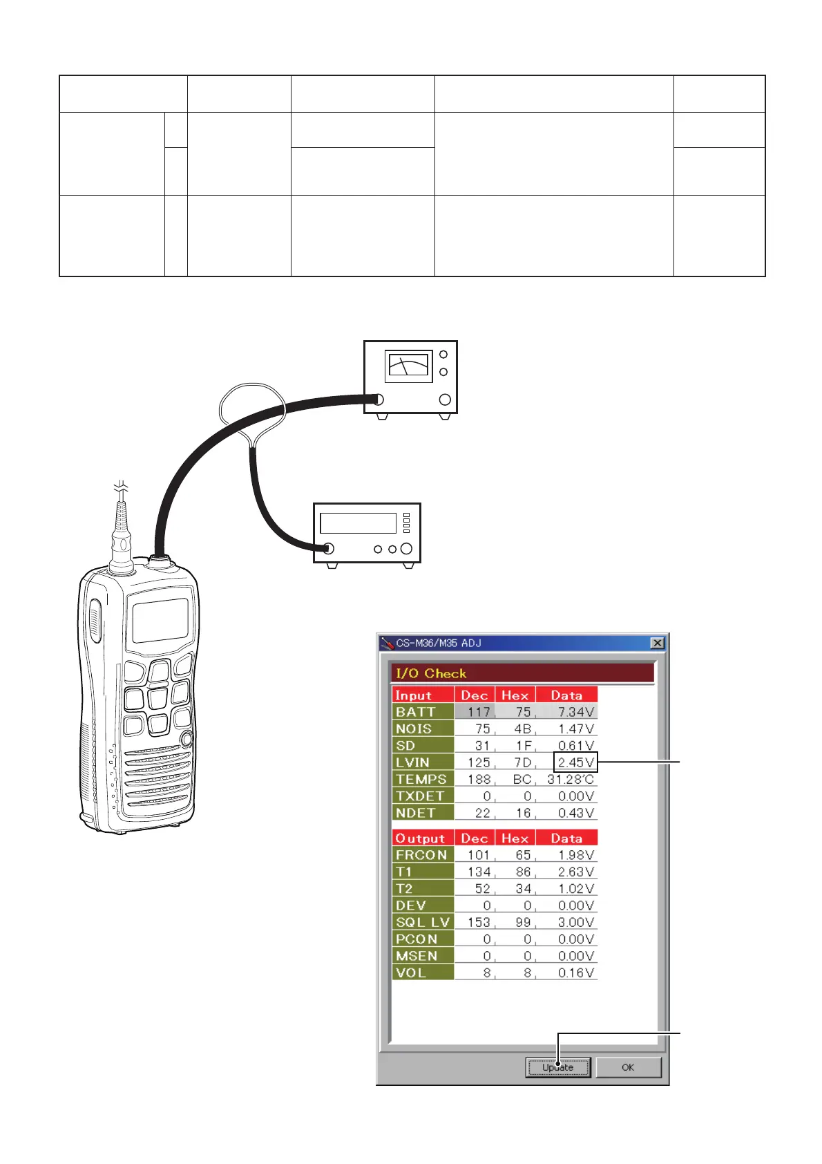
1) Connect an RF power meter (or a
Dummy load) to the antenna connector.
2) Verify that the lock voltage is in the
specified range on the "I/O check
window" (see the illust below).
1.9–2.9 V
(Verify)
2 • CH. : 16
• TX power : Low
• Transmitting
1.8–2.8 V
(Verify)
REFERENCE
FREQUENCY
1
[Ref. Freq.]
• CH. : 16
• TX power : Low
• Transmitting
1) Connect an RF power meter (or a
Dummy load) to the antenna connector.
2) Loose couple a Frequency counter to
the antenna connector.
3) Adjust the TX frequency.
156.8000 MHz
5-2 FREQUENCY ADJUSTMENTS
RF POWER METER
(10 W/50 Ω)
JIG cable
(Loose Coupling)
FREQUENCY COUNTER
(0.1–300 MHz)
LOCK VOLTAGE
I/O CHECK WINDOW
Click to reload
the parameter
(The values shown in the above screen are example only.
Each transceiver has their own values.)
Select an adjustment item using [
↑
] / [
↓
] keys, then set to the specifi ed value using [
←
] / [
→
] keys on the connected PC’s keyboard.

 Loading...