• TX AF AND MODULATION CIRCUITS
• TX AMPLIFIERS AND APC CIRCUIT
4 - 2
4-2 TRANSMITTER CIRCUITS
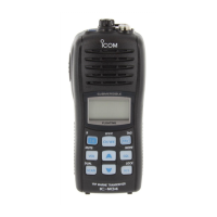
TX AF CIRCUITS
AF signals from the microphone (MIC signals) are passed
through the MIC line SW (IC260A) and amplified by MIC
AMP (IC200B), then passed through the MIC mute SW
(IC260C).
The MIC line SW (IC260A) selects the MIC signal path (from
int. MIC or from ext. MIC), and the MIC mute SW (IC260C)
disconnects the MIC line in receiving.
The MIC signals from the MIC mute SW (IC260C) are
adjusted its amplitude (=deviation) by the D/A converter
(IC190), and pre-emphasized by R201 and C385 to obtain
+6 dB/oct of frequency response.
Pre-emphasized MIC signals are amplitude-limited by the
limiter (IC200A) to prevent over deviation, and fi ltered by the
splatter fi lter (IC200D) to remove 3 kHz and higher signals,
then applied to the VCO for frequency modulation.
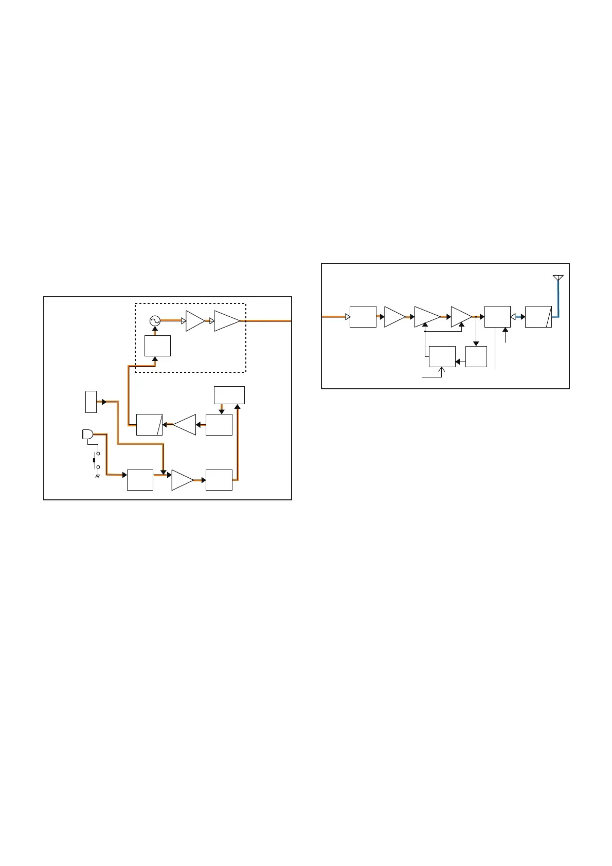
TX AMPLIFIERS
The frequency-modulated signal from the VCO (TX signal)
is passed through the LO SW (D50), and amplified by the
buffer AMP (Q50), driver AMP (Q53) and power AMP (Q54)
in sequence, to obtain TX output power.
APC CIRCUIT
A portion of TX output signal is rectified by D91 to be
converted into the DC voltage which corresponds to TX
power level.
IC50 compares the detected voltage and TX power setting
voltage from D/A converter (IC190). The resulting voltage
from IC50 controls the gain of both the driver (Q53) and the
power (Q54) AMPs to keep the TX output power stable.
To LO switch
BUFFBUFF
LPF
LIMIT
AM P
MIC
AMP
MIC LINE
SW
MIC
MUT E
Q24
Q23
Q 21,Q22
MOD
MUT E
PRE
ENPHA
D/A
MIC
J250
VCO
Q20
IC190
IC200A
IC200D
IC200B
[PTT]
Int. MIC
[SP MIC]
D20
D
21
D22,D23
INMIC
EXTMIC
MOD
IC260A
IC260C
MC250
S250
LPF
ANT
SW
ANTENNA
J1
PWR
AM P
DRIVE
PRELO
SW
BUFF
From VCO
APC
CTRL
T5V
D52
Q53
Q54
D50
Q50
PWR
DET
D91
IC50
D90
Q357
PCON

 Loading...