4 - 1
1ST IF, 2ND IF AND DEMODULATOR CIRCUITS
• 1ST IF CIRCUITS
The RX signals are mixed with 1st LO signals to be
converted into the 21.7 MHz 1st IF signal at the 1st mixer
(Q150). The converted 1st IF signal is filtered by the crystal
filter (FI150, 151) to remove unwanted out-of-band signals.
The filtered 1st IF signal is amplified by the 1st IF AMP
(Q151), then applied to the IF IC (IC170, pin 16).
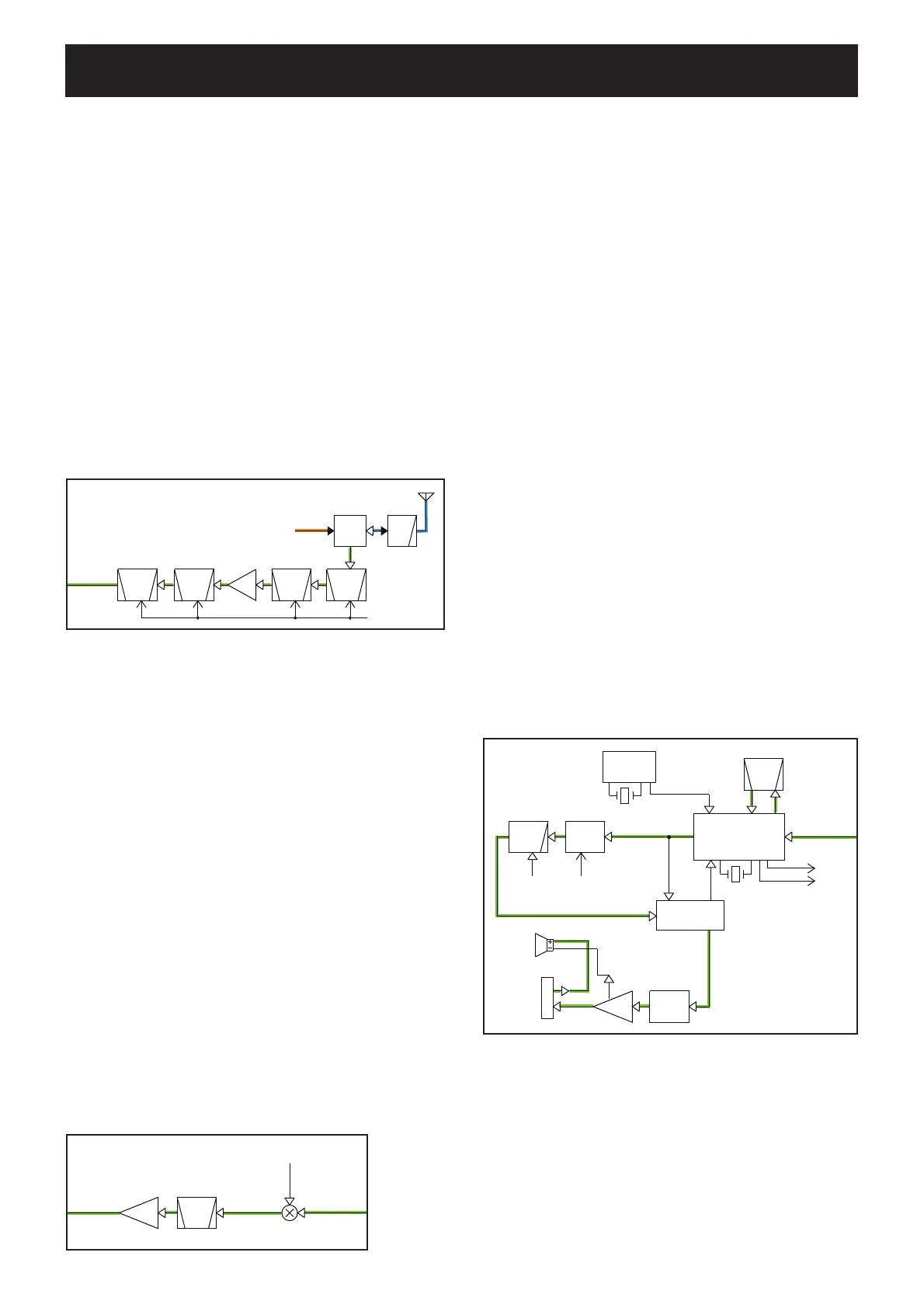
• 2ND IF AND DEMODULATOR CIRCUITS
IC170 is an IF IC contains 2nd local oscillator, 2nd mixer,
limiter and quadrature detector in its package.
The 21.25 MHz reference frequency signal from the PLL
IC (IC1, pin 2) is applied to the IF IC (IC170, pin 2) as the
2nd LO signal, and mixed with 21.7 MHz 1st IF signal from
the 1st AMP (Q151). The resulting signal of 450 kHz 2nd IF
signal is output from pin 3 of IC170.
The 2nd IF signal is filtered by external ceramic filter (FI170)
to extract 450 kHz signal only, then applied to internal
quadrature detector and frequency-demodulated. The
demodulated AF signals are output from pin 9.
4-1 RECEIVER CIRCUITS
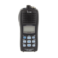
RF CIRCUITS
RF circuits consist of RF fi lters, antenna switch (ANT SW),
RF amplifi er (RF AMP), etc., and extracts and amplifi es the
signal of frequency which is desired to receive.
• ANTENNA SWITCHING CIRCUIT
The RF signals from the antenna are passed through the
LPF (L81, 82, C83–86, 89) and antenna SW (D52, 90, L90,
C90, 91), then applied to the RF AMP (Q90) via the 2-staged
tuned BPF (D92, 93, L92, 93, C95, 97–100, C117).
• RF AMPLIFIER
The filtered RX signals are amplified by the RF AMP (Q90),
and passed through another 2-staged BPF (D130, 131, L96,
97, 110, 112–115) to remove unwanted signals. The filtered
signals are applied to the 1st mixer (Q150).
The quadrature detector is a frequency demodulator which
uses a discriminator (X170) as a phase delayer, and
provides demodulation without any adjustment.
SQUELCH CIRCUIT
A portion of AF signals from the IF IC is level-adjusted by
the D/A converter (IC190), and applied to the noise amplifer
(IC170, R174–176, C179, 180).
Only noise components (approx. 30 kHz signal) are
amplified by the noise amplifier, and rectified by internal noise
detector to be converted into DC voltage corresponding
to noise level; the squelch voltage. The squelch voltage is
applied to the A/D port of the CPU (IC360). The CPU (IC360)
compares input voltage and preset squelch level to control
audio signals ON/OFF (emit/mute).
RX AF CIRCUITS
The demodulated AF signals from the IF IC (IC170, pin 9) are
passed through the AF mute SW (IC260) and LPF (IC200C,
R271–273, C264, 265). The filtered AF signals are passed
through another LPF (R279, C266) to remove 3 kHz and
higher signals, and level-adjusted by the D/A converter (IC190),
and de-emphasized by R286, C285 to obtain –6 dB/oct. of
frequency response, then applied to AF power amplifier (IC362).
IC362 is an AF power amplifier IC which can provide 0.35 W
of output power with 8 ohms load, or 0.7 W of output power
with 16 ohms load.
• RF CIRCUITS
• 2ND IF, DEMODULATOR AND RX AF CIRCUITS
• 1ST IF CIRCUITS
SECTION 4
CIRCUIT DESCRIPTION
LPF
ANT
SW
ANTENNA
BPF
RF
AMP
BPF BPFBPF
To 1st mixer
D131
D
TX CIRCUITS
92
D52
Q90
D93
D90
D130
T1CON
BPF
IF
AMP
21.7MHz
1st IF signal
FI150
Q151
To IF IC
From RF AMP
1st LO signals
from VCO
Q150
FI151
X170
450KHz
BPF
LPF
AF
AM P
X1
21.25MHz
AF
MUT E
From 1st IF AMP
IC1
PLL IC
DE -
ENPHA
IF IC
D/A IC
SPO
AF OUT
J250
IC170
FI170
450KHz
IC190
IC362
IC200C
VOLIN
VOL
BEEP
SQLO
SQLI
RSSI
NOISE LEVEL
21.25 MHz
2ND LO signal
DET
Int. SP
Ext. SP
NJM2073M
IC260D
DETMS
SP1

 Loading...