3 - 1
SECTION 3
DISASSEMBLY INSTRUCTION
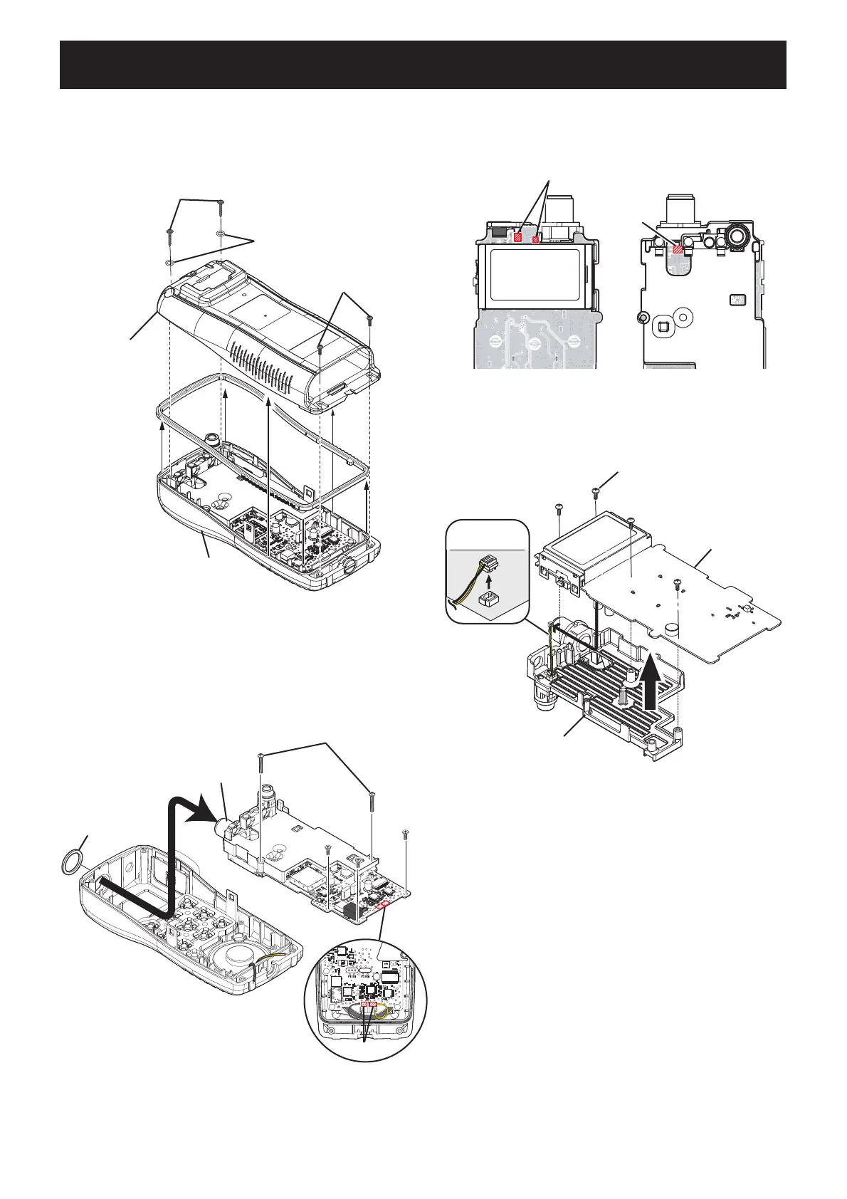
1. REMOVING FRONT PANEL
• Unscrew 4 screws from the rear panel, and remove
the rear panel from the front panel.
NOTICE: NOT to lost 2 o-rings.
3. REMOVING MAIN UNIT
1) Unsolder 2 points from the top side, and 1 point from the
bottom side.
2. REMOVING CHASSIS
1) Unsolder 2 points from the speaker.
2)
Unscrew ANT nut from the antenna connector, and 5 screws
from the MAIN UNIT.
3) Take off the chassis with MAIN UNIT from the front panel
in the direction of the arrow.
REAR PANEL
O-ring
Screw
Screw
FRONT PANEL
MAIN UNIT
CHASSIS
Screw x4
MICROPHONE
CABLE
Unsolder
Unsolder
TOP SIDE
TOP SIDE
BOTTOM SIDE
MAIN UNITMAIN UNIT
MAIN UNIT
Screw
(short) x3
Screw (long)
Unsolder
ANT NUT
ANT CONNECTOR
2) Unscrew 4 screws from the MAIN UNIT.
3) Disconnect the microphone cable from the MAIN UNIT.
4) Take off the MAIN UNIT from the chassis.

 Loading...