4 - 1
SECTION 4 CIRCUIT DESCRIPTION
4-1 RECEIVER CIRCUITS
4-1-1 ANTENNA SWITCHING CIRCUIT (MAIN UNIT)
The antenna switching circuit functions as a low-pass filter
while receiving and as resonator circuit while transmitting.
The circuit does not allow transmit signals to enter the
receiver circuits.
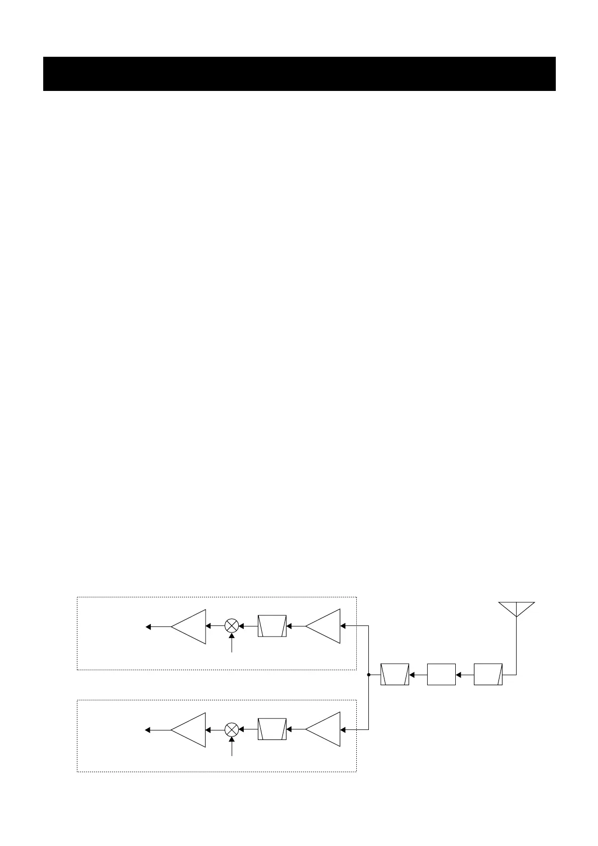
Received signals enter the MAIN unit from the antenna con-
nector and pass through the low-pass filter (L1, L2, C1, C3,
C5). The signals are then applied to the RF circuit via the
antenna switching circuit (D1, L3, L4, C7–C9).
4-1-2 RF CIRCUIT (MAIN UNIT)
The RF circuit amplifies signals within the range of frequen-
cy coverage and filters out-of-band signals.
The signals from the antenna switching circuit pass through
the tunable bandpass filter (L11, C23–C25) which the object
signals are led to each RF amplifier of channel 70 circuit
(Q7) or other channels (except channel 70) circuit (Q1).
• CHANNEL 70 CIRCUIT
The amplified signals from the RF amplifier (Q7) are applied
to the 4-stage bandpass filter (L31–L34, C407, C408,
C410–C423) to suppress unwanted signals and improve the
selectivity. The signals are then applied to the 1st mixer cir-
cuit for channel 70.
• OTHER CHANNELS CIRCUIT
The amplified signals from the RF amplifier (Q1) are applied
to the 4-stage bandpass filter (L12–L15, C33, C34,
C36–C48) to suppress unwanted signals and improve the
selectivity. The signals are then applied to the 1st mixer cir-
cuit for other channels.
4-1-3 1ST MIXER AND 1ST IF CIRCUITS
(MAIN UNIT)
The 1st mixer circuit converts the received signal into a fixed
frequency of the 1st IF signal with a 1st LO (VCO output) fre-
quency. By changing the 1st LO frequency, only the desired
frequency will pass through a pair of crystal filters at the next
stage of the mixer.
• CHANNEL 70 CIRCUIT
The signals from the RF circuit are mixed with the 1st LO
signals at the 1st mixer circuit (D21, L48, L49) to produce a
21.7 MHz 1st IF signal.
The 1st IF signal is amplified at the 1st IF amplifiers (Q8,
Q9), and then passes through the pair of crystal bandpass
filters (FI4, FI5) to suppress out-of-band signals. The filtered
signal is then amplified at the 2nd IF amplifier (Q10), and is
then applied to the 2nd mixer circuit (IC6).
• OTHER CHANNELS CIRCUIT
The signals from the RF circuit are mixed with the 1st LO
signals at the 1st mixer circuit (D11, L18, L19) to produce a
31.05 MHz 1st IF signal.
The 1st IF signal is amplified at the 1st IF amplifiers (Q3,
Q4), and then passes through the crystal bandpass filter
(FI1) to suppress out-of-band signals. The filtered signal is
then amplified at the 2nd IF amplifier (Q2), and is then
applied to the 2nd mixer circuit (IC1).
 Loading...