5 - 3
*This output level of a standard signal generator (SSG) is indicated as SSG’s open circuit.
5-3 RECEIVER ADJUSTMENTS
SENSITIVITY
(Except
channel 70)
(Channel 70)
ADJUSTMENT
ADJUSTMENT ADJUSTMENT CONDITION
MEASUREMENT
VALUE
POINT
UNIT LOCATION UNIT ADJUST
1
2
• Operating channel : ch 16
• Connect a tracking generator’s
output to the antenna connector
and set as:
Level : 7.1 mV*
(–30 dBm)
• Operating channel : ch 16
• Connect an SSG to the antenna
connector and set as:
Frequency : 156.800 MHz
Level : 10 µV*
(–97 dBm)
Modulation : 1 kHz
Deviation : ±3.5 kHz
• Set the internal speaker OFF in
the SET mode, and connect a
distortion meter with a 4 Ω load to
[EXT SP] receptacle.
• Receiving
MAIN
MAIN
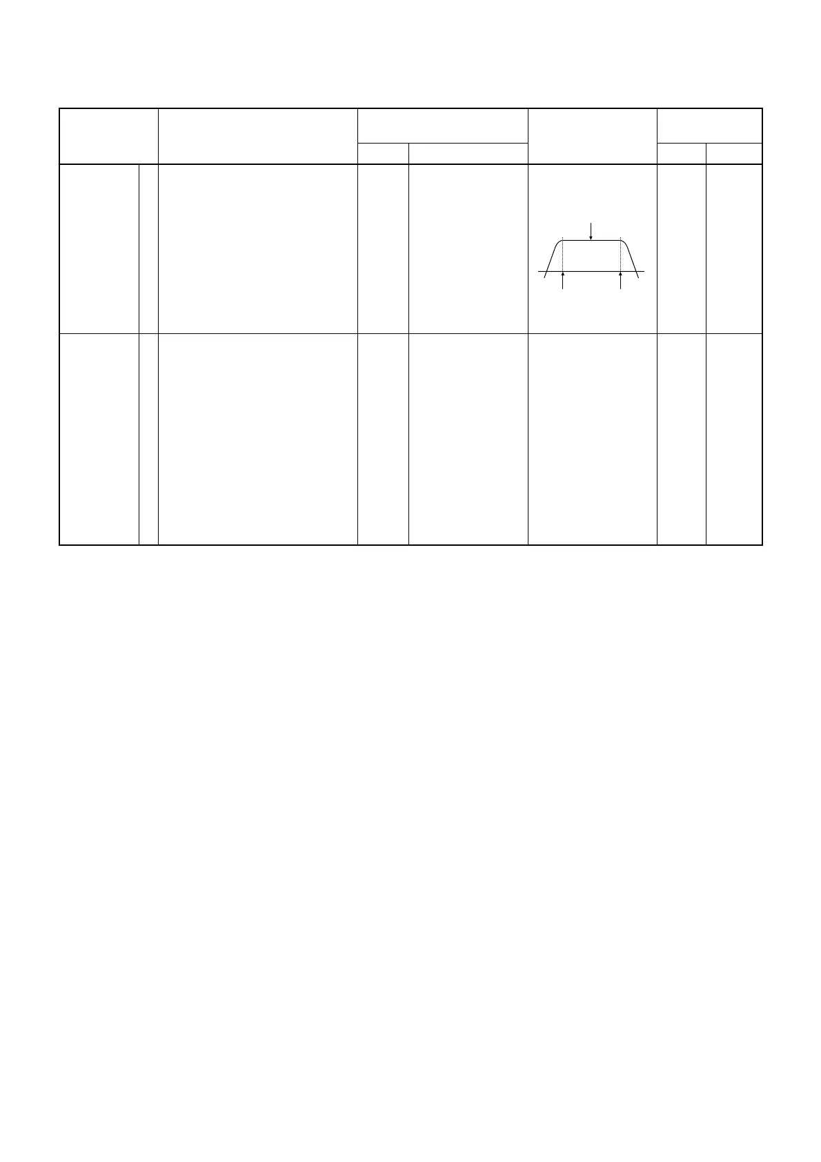
Connect a tracking
generator’s input to
the MAIN unit; J3.
Connect a DC volt-
meter to check point
CP3.
Set the flat wave
form as shown below.
Maximum voltage
MAIN
MAIN
L11
L12
L13
L14
L15
L31
L32
L33
L34
 Loading...