4 - 6
4-6 POWER SUPPLY CIRCUITS
4-6-1 VOLTAGE LINE (MAIN UNIT)
4-7 PORT ALLOCATIONS
4-7-1 EXPANDER IC (AF unit; IC18)
4-7-2 EXPANDER IC (AF unit; IC17)
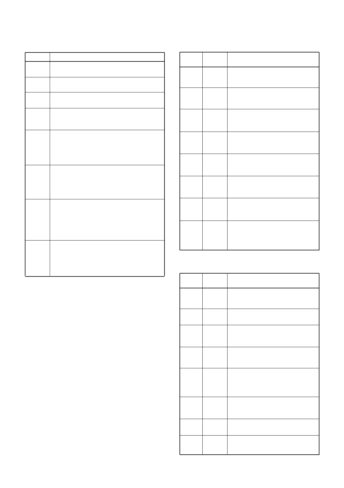
LINE
13.8
HV
HVS
VCC
8V
5V
T8
R8
DESCRIPTION
The 13.8 V from the connected DC power sup-
ply.
Same voltage as the HV line which is passed
through the [PWR] switch (LOGIC unit; S1).
Same voltage as the HVS line which is passed
through the power controller (AF unit; RL1).
Same voltage as the 13.8 V line, and is applied
to the AF power amplifiers (AF unit; IC3, IC10),
LOGIC unit, etc.
Common 8 V converted from the VCC line at the
+8V regulator circuit (AF unit; IC1). The output
voltage is applied to the T8 controller (MAIN unit;
Q36, Q36), +5 regulator (AF unit; IC2), R8 regu-
lator (AF unit; Q1, Q2), etc.
Common 5 V converted from the 8V line at the
+5 regulator circuit (AF unit; IC2). The output
voltage is applied to the buffer amplifiers (AF
unit; IC19, Q14), expander ICs (AF unit; IC17,
IC18), etc.
Transmit 8 V controlled by the T8 control circuit
(MAIN unit; Q35, Q36) using the “SEND” signal
from main CPU. The output voltage is applied to
the pre-dirve (MAIN unit; Q28), YGR amplifier
(MAIN unit; Q30), APC controller (MAIN unit;
IC14), etc.
Receive 8 V controlled by the R8 control circuit
(AF unit; Q1, Q2) using the RCV signal from
main CPU. The controlled voltage is applied to
the bandpass filter (AF unit; Q11, Q12), buffer
and IF amplifiers (AF unit; Q2 and Q23), etc.
4
5
6
7
11
12
13
14
MICS2
MICS1
SPS2
SPS1
SP
BPLVL
RCV
HLC
Outputs HM-127/2 control signal.
High : While transmitting via the
HM-127/2.
Outputs HM-127/1 control signal.
High : While transmitting via the
HM-127/1.
Outputs HM-127/2 control signal.
High : While receiving via the
HM-127/2.
Outputs HM-127/1 control signal.
High : While receiving via the
HM-127/1.
Outputs the internal speaker (FRONT
unit; SP1) control signal.
High : The speaker is activating.
Outputs beep audio level control sig-
nal.
Low : Beep audio level is maximum.
Outputs the R8 regulator (AF unit; Q1,
Q2) control signal.
High : While receiving.
Outputs the Hailer speaker TX/RX
select signal.
High : While transmitting via the
Hailer speaker.
Pin Port
Description
number name
4
5
6
7
11
12
13
14
STRU
AFSUB
INCMH
INCHM
MIC/DSC
HAILIN
FOGC
HAILOUT
Outputs scrambler unit bypass control
signal.
High : Bypassing the scrambler unit.
Outputs sound signals to the HM-127.
High : Sounding from HM-127.
Outputs voice signals from IC-M602 to
HM-127 using intercom function.
High : While receiving.
Outputs voice signals from HM-127 to
IC-M602 using intercom function.
High : While transmitting.
Outputs MIC/DSC modulation circuit
control signal.
High : While the DSC signal is mod-
ulated.
Outputs the microphone select signal.
High : While using the hailer speak-
er.
Outputs fog horn control signal.
High : Fog horn is ON.
Outputs the microphone select signal.
High : While using the HM-136.
Pin Port
Description
number name
 Loading...