4 - 2
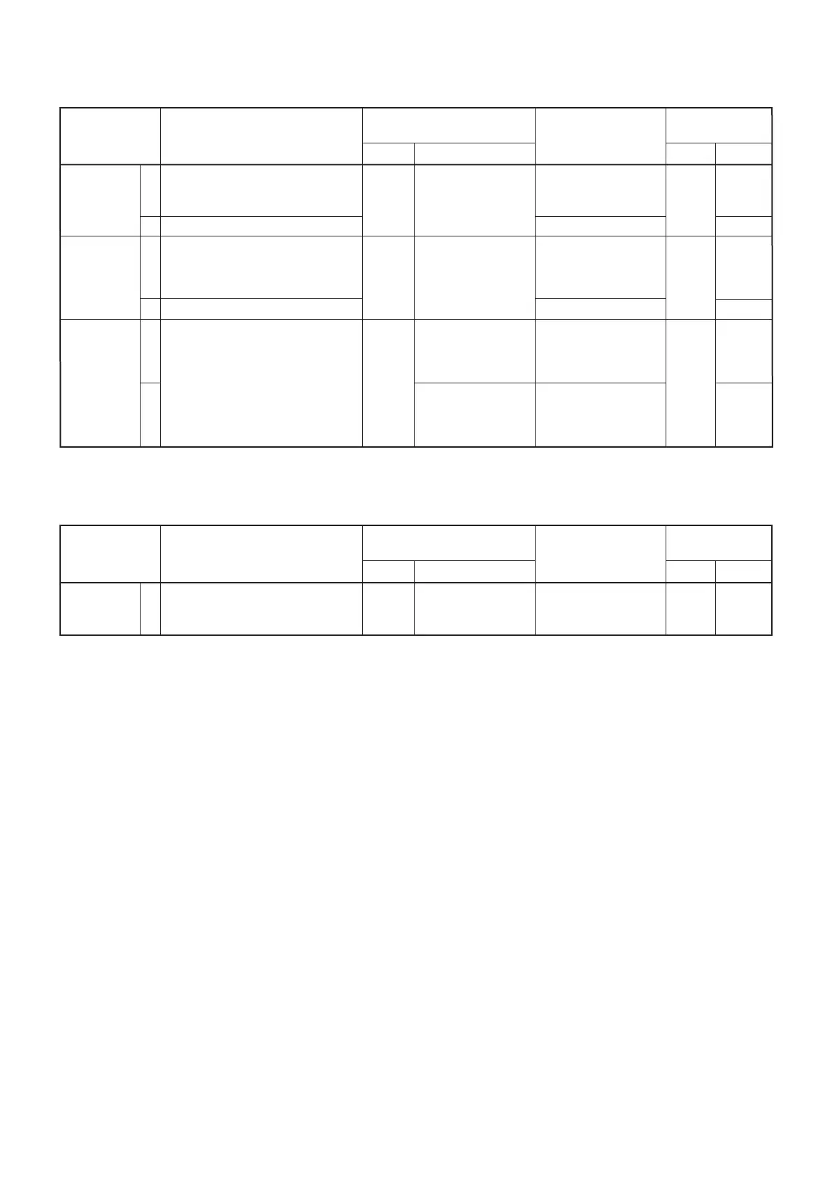
4-2 PLL ADJUSTMENTS
REFERENCE
LOOP LOCK
VOLTAGE
MAIN
LOOP LOCK
VOLTAGE
REFERENCE
FREQUENCY
ADJUSTMENT
ADJUSTMENT ADJUSTMENT CONDITION
MEASUREMENT
VALUE
POINT
UNIT LOCATION UNIT ADJUST
1
2
1
2
1
2
• Display frequency : 7.9999 MHz
• Mode : J3E
• Receiving
• Display frequency : 0.0300 MHz
• Display frequency : 0.5000 MHz
• Receiving
• Display frequency : 29.9999 MHz
• Wait for 5 minutes after power ON.
• Terminate P3002 on the PLL unit
to ground with a 50 Ω resister.
• Receiving
PLL
PLL
PLL
Connect a digital
multimeter or oscillo-
scope to check point
J3004.
Connect a digi-
tal multimeter or
oscilloscope to
check point J3005.
Connect an RF volt-
meter to check point
P3002.
Connect a frequency
counter to check
point P3002.
3.2 V
More than 1.5 V
4.0 V
More than 1.0 V
Maximum level
(More than +2 dBm)
60.000000 MHz
PLL
PLL
PLL
C3049
Verify
L3024
[GMDSS]
R3223
[Others]
Verify
L3004
L3005
X3002
[GMDSS]
L3003
[Others]
4-3 POWER VOLTAGE ADJUSTMENT
13.6 V
VOLTAGE
([EUR] only)
ADJUSTMENT
ADJUSTMENT ADJUSTMENT CONDITION
MEASUREMENT
VALUE
POINT
UNIT LOCATION UNIT ADJUST
1 • Turn power ON. MAIN Connect a DC volt-
meter to L106.
13.6 V REG R8013
[GMDSS]: [GEN-23], [EUR-22] [Others]: [GEN-21], [GEN-22], [EUR-21]
[EUR]: [EUR-21], [EUR-22]

 Loading...