3 - 4
3-2-6 POWER AMPLIFIER CIRCUIT
(PA150W BOARD)
This circuit provides a stable 150 W (at 13.6 V) of output
power. The RF signal from the MAIN unit is amplified at the
pre-driver (Q4008), drivers (Q4001, Q4002), and power
amplifiers (Q4003, Q4004).
The driver and power amplifiers form class AB push-pull
circuits. Bias voltage to these transistors is produced by
diodes (D4001–D4003) which have temperature junctions
with the transistors.
The amplified signal is then applied to one of eight low-
pass filters to suppress high harmonic components. The
filtered signal passes through the power detector circuit
(FILTER board; L4341) and transmit/receive switching relay
(FILTER board; RL4317) and is then applied to the antenna
connector.
• LOW-PASS FILTERS USED (FILTER BOARD)
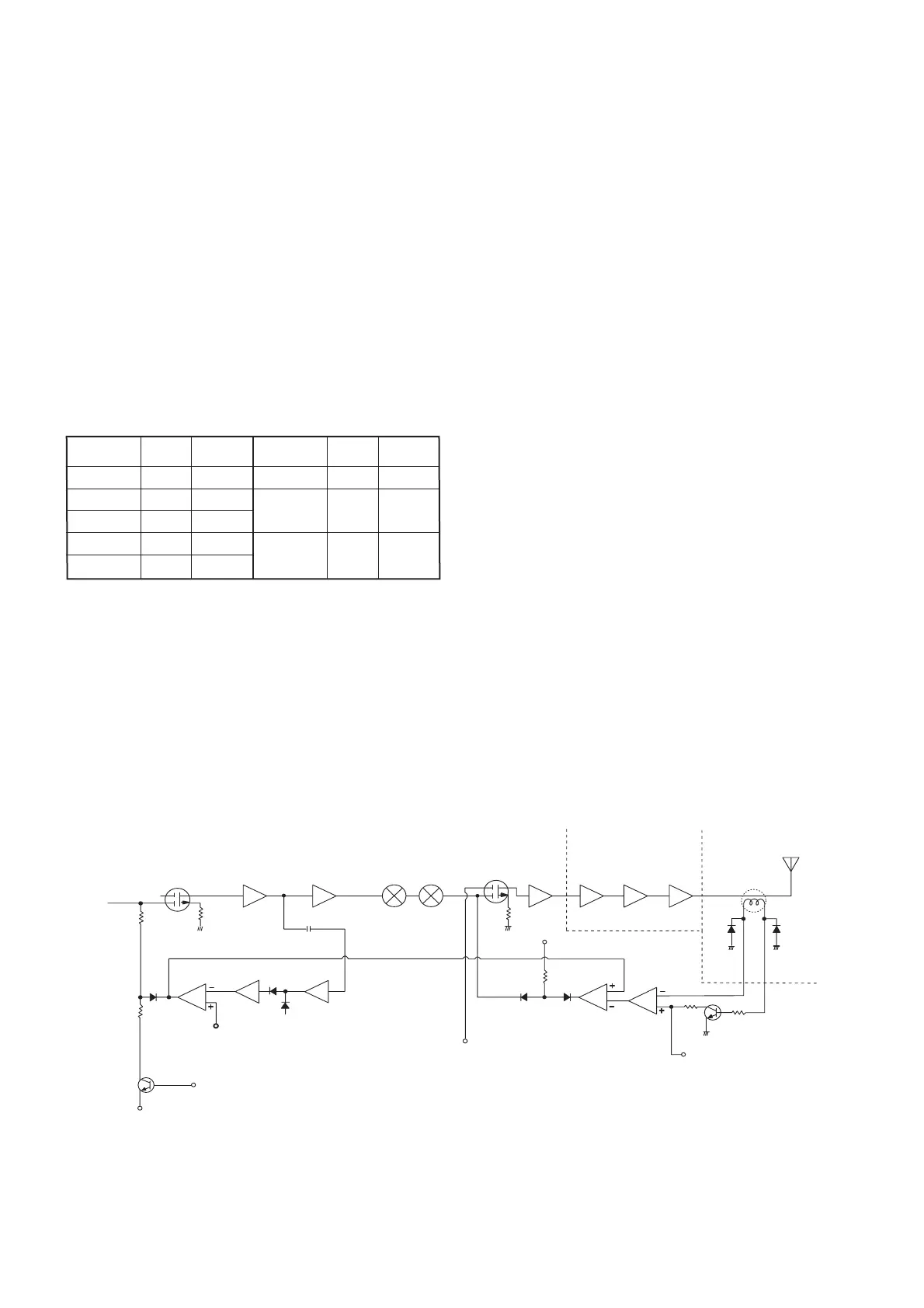
3-2-7 ALC CIRCUIT
The transceiver has two ALC (Auto Level Control) loops for
constant output power over all marine bands and for high
power setting.
(1) IF ALC CIRCUIT (MAIN UNIT)
A portion of the IF signals from the IF amplifier (Q17) is
applied to the IF ALC circuit. The signal is amplified at
Q126 and then detected at the ALC detector (D46). The
detected signal is amplified at the ALC amplifier (IC17b)
and is then applied to the comparator (IC17a).
The reference voltage for the comparator is set by R184.
The antenna tuning control voltage (TUN8) and low power
set signal (POC1) are also affected by the reference volt-
age to decrease the IF signal level.
The comparator output controls the gate bias of the IF
amplifier (Q19), so that the IF signal level is determined by
the reference voltage of the comparator (IC17a).
(2) RF ALC CIRCUIT (FILTER BOARD)
The RF output power level is detected at D4309 of the
power detector circuit (FILTER board; L4341, D4309,
D4310). The detected signal (“FOR” signal) is applied to
the RF ALC amplifier (MAIN unit; IC16a).
The amplified signal enters the transmit gain controller
(IC16b) which functions as an inversion amplifier. The gain
controller decrease the gain of the IF amplifier (MAIN unit;
Q2) to constant output power from differential amplifier
gains which are occurred by their frequency characteristics.
The bias voltage of the RF ALC amplifier (IC16a) is con-
trolled by the low power control signal (POC1 for 20 W,
POC2 for 60 W) and APC signal.
Q19 Q18 Q17
IF ALC CIRCUIT
IC17a IC17b
Q126
20 W low power set (Q132)
Current APC
– 5 V
High power set (R184)
Low power during tune (Q28)
D52 Q3, Q4
Q2
Q1
8 V
Current APC control (Q111)
Low power during tune (Q21, Q22)
RF ALC CIRCUIT
Q4008
Q4001
Q4002
Q4003
Q4004
L4313
IC16b
IC16a
Q23
60 W power set (Q24)
20 W power set (Q25)
D4309
FOR
REF
D4310
MAIN UNIT PA UNIT FILTER UNIT
Frequency
(MHz)
0.5–1.999
2–2.999
3–4.999
5–6.999
7–9.999
Frequency
(MHz)
10–13.999
14–17.999
18–19.999
20–21.999
22–23.999
24–29.999
Control
signal
L5
L6
L7
Control
signal
L0
L1
L2
L3
L4
Entrance
Relay
RL4301
RL4303
RL4305
RL4307
RL4309
Entrance
Relay
RL4311
RL4313
RL4315
• ALC CIRCUIT

 Loading...