EasyManuals Logo

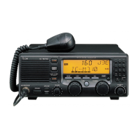
Icom IC-M710 Service Manual

Icom IC-M710
71 pages
To Next Page IconTo Next Page
To Previous Page IconTo Previous Page
Page #60 background imageLoading...
Page #60 background image
8-12 REG BOARD [EUR] only
TOP VIEW
1
8
16
9
P8001
to TERMINAL
board J7001
P8002
GND
13.6/13S
to MAIN
unit J32
[EUR-21]
/to LOGIC
unit J2013
[EUR-22]
HVE
HVO/HV
Add "8000" to each indicated part number
on the unit for the actual number.
NOTE:
8-13 ALARM BOARD except [GEN-21]
TOP VIEW
51015 20 25 30 350
Horizontal
5
10
15
0
20
Vertical
1
to MAIN
unit J29
2
9
10
J5001
GND
GND
GND
GND
GND
GND
5V
GND
ALM8
GND
14
to MAIN
unit J30
13
2
1
J5002
GND
GND
ALMC
GND
TONE
GND
GND
GND
GND
GND
GND
GND
GND
GND
Add "5000" to each indicated part number
on the unit for the actual number.
NOTE:
8 - 13

Table of Contents

Other manuals for Icom IC-M710

Questions and Answers:

Question and Answer IconNeed help?

Do you have a question about the Icom IC-M710 and is the answer not in the manual?

Icom IC-M710 Specifications

General IconGeneral
Output Power150W PEP
Antenna Impedance50 ohms
Power Supply Requirement13.8V DC ±15%
Operating Temperature Range-15°C to +55°C
TypeMarine HF/SSB Transceiver
Frequency Range Transmit1.6 - 27.5 MHz
Frequency Range Receive0.5-30 MHz
ModeSSB, AM
Channels160

Related product manuals