1
30
31 50
100 81
80
30 1
51
100
81
31
50
80
51
1
1
7
4
8
5
W22
[GEN-21], [GEN-22],
[EUR-21] only
P2004 [GEN-23], [EUR-22] only
to MAIN
unit J32
13.6
GND
1
to VR2
board J2501
2
5
6
J2012
5V
CUL
GND
5V
CUL
GND
1
to SENSOR2
board J2701
2
5
6
J2010
UP2
NC
GND
DN2
NC
GND
1
to SENSOR1
board J2601
2
5
6
J2009
UP1
NC
GND
DN1
NC
GND
from PLL-A
unit J3008
14
J2016
NC
GND
NC
13S
1
to VR1
board J2401
2
5
6
J2011
5V
VOL
VOLE
5V
VOL
VOLE
to FRONT
SP2801
13
J2007
SP+
NC
SP
-
HVO/GND
1
2
from TERMINAL
board P7001
[GEN-21], [GEN-22], [EUR-21]
/from TERMINAL
board J7001
[GEN-23]
/from REG
board P8002
[EUR-22]
J2013
HV/13S
HVO/13.6
2
1
to FRONT
S2801
[POWER]
J2014
HV/13S
to MAIN
unit J16
17
J2002
LTXD
LRXD
SPE
SP
GND
13.6
13.6
GND1
2
9
10
to MIC
board J2302
J2008
PTT
MICE
NC
AF2
GND
PTTE
MIC
AF1
AFE
to MAIN
unit J23
41
J2003
MOD
MODE
AFGE
AFG2
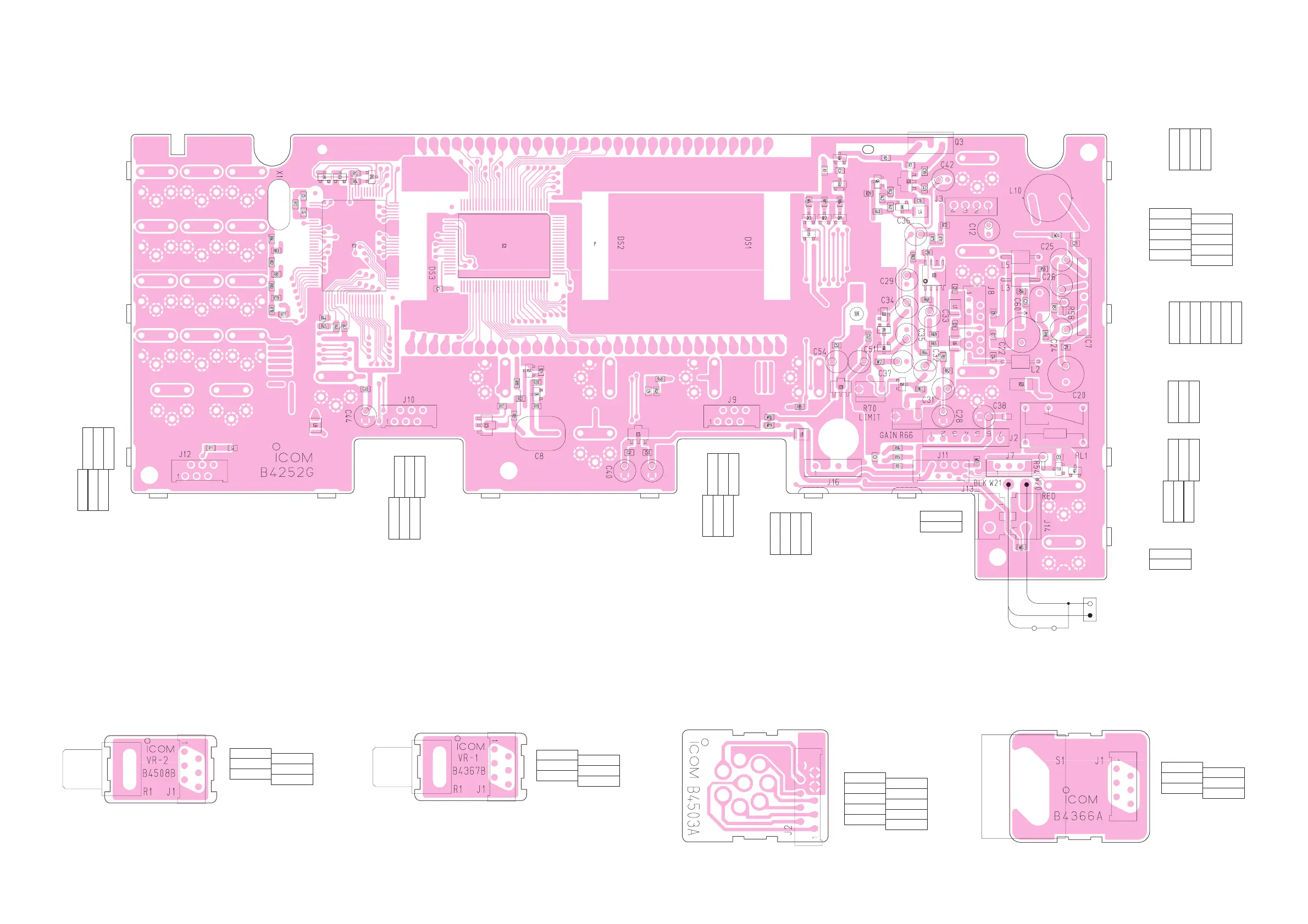
Add "2000" to each indicated part number
on the unit for the actual number.
NOTE:
8 - 2
• BOTTOM VIEW (LOGIC UNIT)
• BOTTOM VIEW (VR2 BOARD) • BOTTOM VIEW (SENSOR1/2 BOARD)• BOTTOM VIEW (MIC BOARD)• BOTTOM VIEW (VR1 BOARD)
GND1
2
5
6
to LOGIC
board J2012
J2501
CUL
5V
GND
CUL
5V
Add "2500" to each indicated part number
on the unit for the actual number.
NOTE:
Add "2600" [SENSOR1] / "2700" [SENSOR2] to each
indicated part number on the unit for the actual number.
NOTE:
GND1
2
5
6
to LOGIC unit J2009
[SENSOR1]
/to LOGIC unit J2010
[SENSOR2]
J2601/J2701
NC
UP1/2
GND
NC
DN1/2
GND10
9
2
1
to LOGIC
unit J2008
J2302
PTT
MICE
NC
AF2
GND
PTTE
MIC
AF1
AFE
Add "2300" to each indicated part number
on the unit for the actual number.
NOTE:
VOLE1
2
5
6
to LOGIC
board J2011
J2401
VOL
5V
VOLE
VOL
5V
Add "2400" to each indicated part number
on the unit for the actual number.
NOTE:

 Loading...