35
5
MEMORY/CALL CHANNELS
■ General
The transceiver has 500 memory channels, 50 scan edge
channels and 5 call channels for storage of often-used fre-
quencies.
Memory channels can be named with 6 characters and as-
signed to 18 banks.
D Memory/call channel contents
The following information can be programmed into memory
or call channels:
• Operating frequency (p. 19)
• Receive mode (p. 21)
• Tuning step (p. 18)
• Duplex direction (DUP or – DUP) with an offset frequency
(p. 31)
• Subaudible tone encoder, tone squelch or DTCS squelch
ON/OFF (pgs. 29, 71)
• Subaudible tone and tone squelch frequencies (p. 70)
• DTCS code with code phase mode (pgs. 65, 70)
• Memory bank (p. 41)
• Memory name (p. 39)
• Scan skip setting (p. 48)
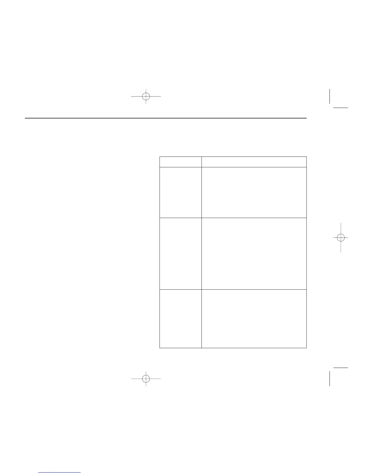
DDefault memory contents example
CHANNEL DESCRIPTION
000–499
(Memory
channel; Mch)
• Regular memory channel
• Default memory channel example
Mch 000 151.000 MHz
Mch 001 145.000 MHz
Mch 002 430.000 MHz
*Mch 003–499 are blank channels.
0A/0B–
24A/24B
(Scan edge
channel)
• Program scan edge channel
25 pairs (50 channels)
• Default scan edge example
0A: 1110.495 MHz 0B: 440.000 MHz
1A: 1150.000 MHz 1B: 1152.000 MHz
2A: 1144.000 MHz 2B: 1146.000 MHz
3A: 1430.000 MHz 3B: 1440.000 MHz
11
*4A/4B–24A/24B are blank channels.
C0–C4
(Call channel)
• Calling channel for amateur bands
•
Can be used as regular memory channel
• Default call channel example
C0 151.000 MHz
C1 145.000 MHz
C2 430.000 MHz
*C3 and 4 are blank channels.
IC-T90A_IM.qxd 02.6.6 08:44 AM Page 38 (1,1)

 Loading...