3
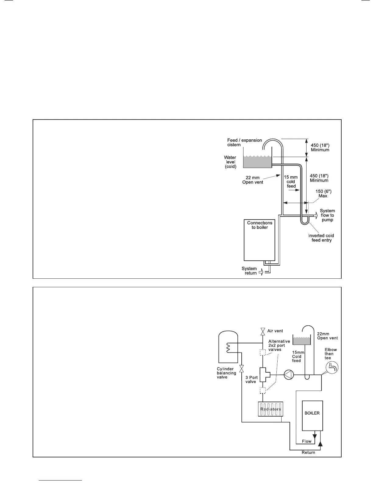
OPEN VENT SYSTEM REQUIREMENTS
4
SCHEMATIC PIPEWORK AND SYSTEM BALANCING
minimum boiler output, must be provided with twin lockshield valves so that this minimum heating load is always available (see
footnote re. thermostatic radiator valves).
Return & ow
connections
load 30 - 60 = 22 mm
load 70 - 80 = 28 mm
Balancing
1. Set the programmer to ON for both CH and HW. Turn the cylinder
thermostat down. Close the manual or thermostatic valves on
all radiators, leaving the twin lockshield valves (on the radiators
referred to above) in the open position. Turn up the room thermostat
temperatures not more than 20
o
C apart. These valves should now
be left as set.
2. Open all manual or thermostatic radiator valves and adjust the
lockshield valves on remaining radiators to give around 11
o
C
temperature drop at each radiator.
3. Turn up the cylinder thermostat and adjust the cylinder balancing
water loop in circuit a differential temperature of 20
o
C across the
boiler is not exceeded.
4. Adjust room and cylinder thermostats and programmer to NORMAL
settings.
the boiler as possible. The cold feed entry should be inverted and MUST be
positioned between the pump and the vent, and not more than 150mm (6”)
away from the vent connection.
Note. Combined feed and vent pipes may also be tted.
There should be a minimum height 450mm (18”) of open vent above the
cistern water level. If this is not possible refer to Frame 5. The vertical distance
between the highest point of the system and the feed/expansion cistern water
A suitable pump is a domestic circulator capable of providing a maximum 11
o
C
(20
o
F) temperature differential across the boiler with the whole of the heating
circuit open (e.g. Grundfos UPS 15/50, 15/60 or equivalent). With the minimum
o
C. (18
o
C
The vertical distance between the pump and feed/expansion cistern MUST
comply with the pump manufacturer’s minimum requirements, to avoid
cavitation. Should these conditions not apply either lower the pump position or
Ideal Boilers.
ELECTRICAL SUPPLY
WARNING.
This appliance must be earthed.
Wiring external to the appliance MUST be in accordance with
regulations which apply. For Ireland reference should be made to
The point of connection to the mains should be readily accessible
and adjacent to the boiler.
N.B. THE FAN VOLTAGE IS 325V DC.
CONDENSATE DRAIN - Refer to Frames 13, 15 and 18
A condensate drain is provided on the boiler. This drain must be
condensate drainage system MUST be made of plastic - no other
materials may be used.
IMPORTANT.
Installation must be in accordance with BS 6798.
The drain outlet on the boiler is sized for standard 21.5mm (3/4”)
brands of pipework.
 Loading...