17
CONDENSATE DRAIN
T
1st time or after maintenance.
a. Where a new or replacement boiler is being installed, access to
an internal ‘gravity discharge’ termination should be one of the
main factors considered in determining boiler location.
e. All horizontal pipe runs, must fall a minimum of 45mm per metre
away from the Boiler.
and insulated with Class “O” waterproof pipe insulation.
g. All installations must be carried out in accordance to the
relevant connection methods as shown in the “Condensate
h. Pipe work must be installed so that it does not allow spillage
into the dwelling in the event of a blockage (through freezing)
i. All internal burrs should be removed from the pipe work and any
In order to minimise the risk of freezing during prolonged very cold
spells, one of the following methods of terminating condensate
drainage pipe should be adopted.
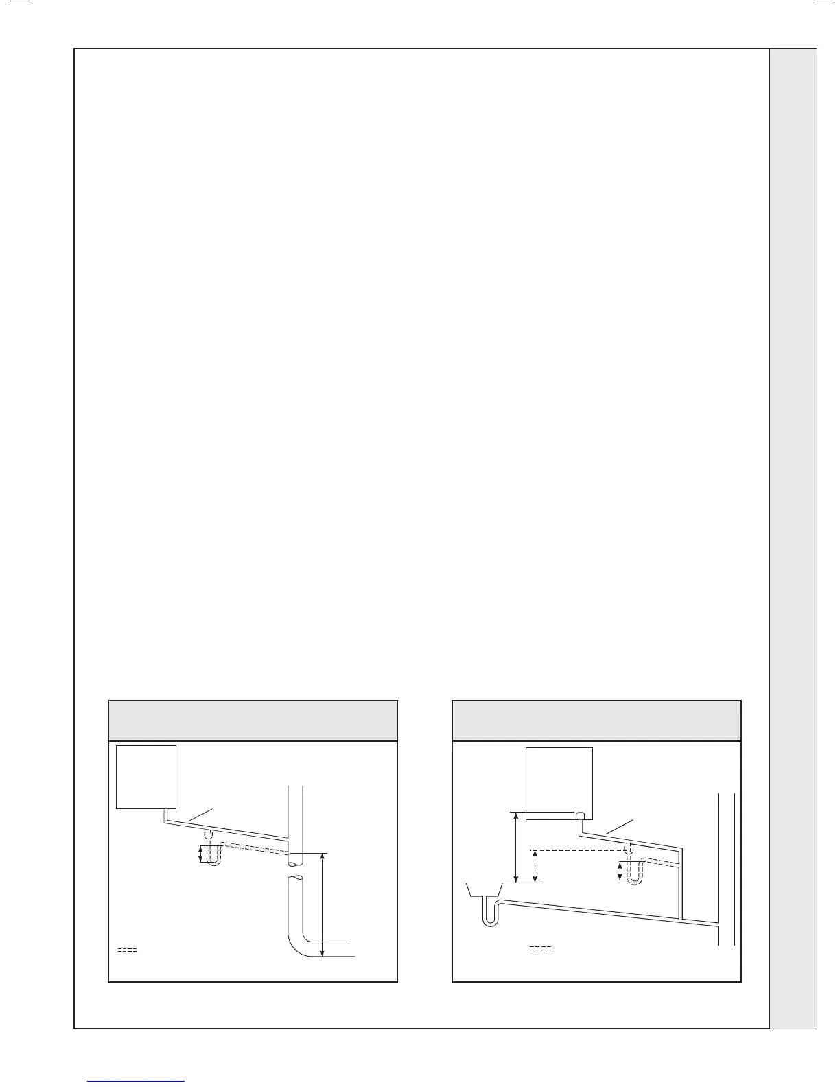
Internal Drain Connections
Wherever possible, the condensate drainage pipe should be routed
to drain by gravity to a suitable internal foul water discharge point
such as an internal soil and vent stack or kitchen or bathroom
waste pipe etc. See Figs 1 and 2.
Condensate Pump
Where gravity discharge to an internal termination is not physically
possible or where very long internal pipe runs would be required
to reach a suitable discharge point, a condensate pump of a
should be used terminating into a suitable internal foul water
discharge point such as an internal soil and vent stack or internal
External Drain Connections
The use of an externally run condensate drainage pipe should
only be considered after exhausting all internal termination options
as described previously. An external system must terminate at a
suitable foul water discharge point or purpose designed soak away.
If an external system is chosen then the following measures must
The external pipe run should be kept to a minimum using the most
direct and “most vertical” route possible to the discharge point, with
no horizontal sections in which condensate might collect.
- For connections to an external soil/vent stack see Fig 4.
Insulation measures as described should be used.
- When a rainwater downpipe is used, an air break must be
installed between the condensate drainage pipe and the
- Where the condensate drain pipe terminates over an open
foul drain or gully, the pipe should terminate below the grating
level, but above water level, to minimise “wind chill” at the open
end. The use of a drain cover (as used to prevent blockage by
leaves) may offer further prevention from wind chill. See Fig 6.
- Where the condensate drain pipe terminates in a purpose
designed soak away (see BS 6798) any above ground
condensate drain pipe sections should be run and insulated as
described above. See Fig 7
Unheated Internal Areas
Internal condensate drain pipes run in unheated areas, e.g. lofts
basements and garages, should be treated as external pipe.
condensate and is shown where this information can be found in
the user manual.
Boiler
with 75mm
sealed
condensate
trap
Min Ø 19mm
Internal pipe
Minimum
connection
height up to 3
storeys
Soil & vent stack
≥ 450
75
Boilers without 75mm sealed
condensate trap must be fitted with
a 75mm trap and visible air break
 Loading...