65
COMBUSTION CHAMBER INSULATION REPLACEMENT (HE15, HE18 and HE24 only)
Ideal Boilers recommends that, for your own comfort and safety and to
comply with good working practice, the procedure described below is
1. Refer to 'Replacement of Components' Frame.
2. Remove the boiler front and sealing panels. Refer to 'Boiler Front
Panel Removal' and 'Boiler Sealing Panel Removal' Frame.
3. Remove the fan / venturi assembly. Refer to 'Fan and Venturi
Assembly removal and cleaning' Frame.
4. Remove the burner. Refer to 'Burner removal and cleaning' Frame.
5.
replacement' Frame.
6.
electrode replacement' Frame.
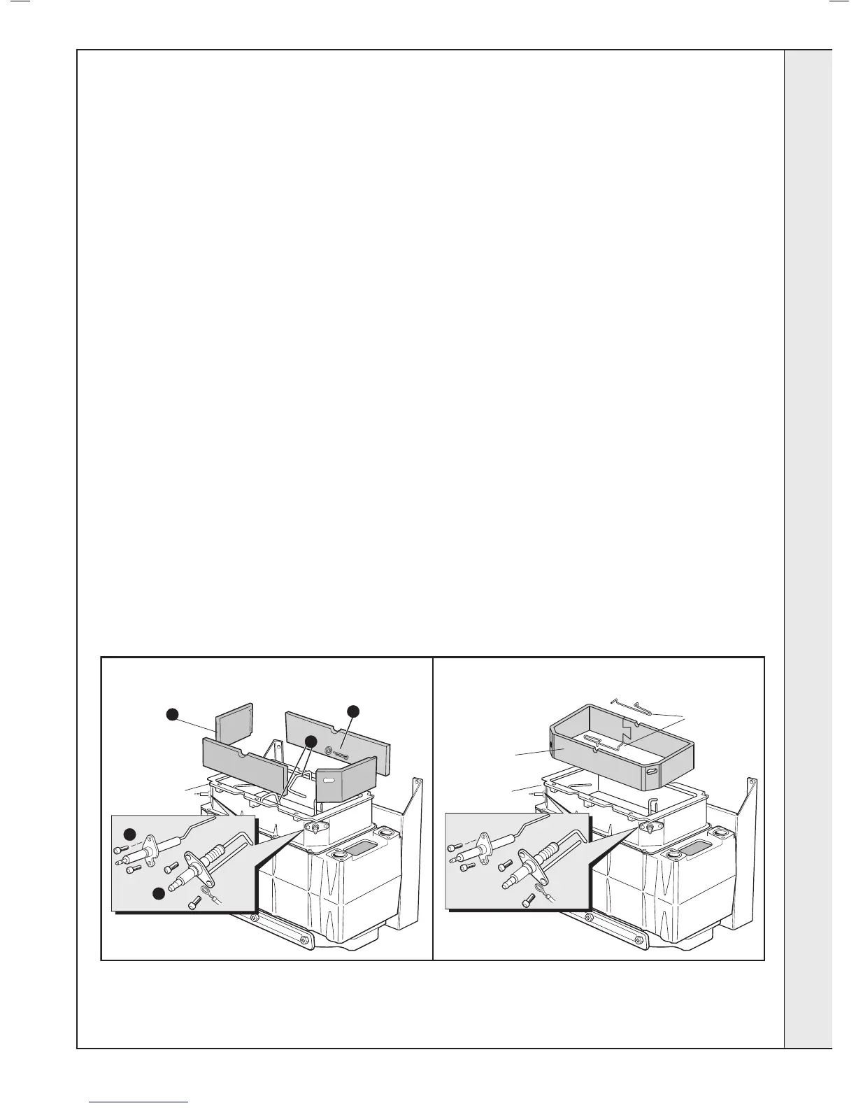
7. Remove the front and rear ionisation probes and discard.
Prior to removal of the board the following protective equipment should
- Face mask supplied with the spare part.
- Gloves supplied with the spare part.
8.
insulation boards.
9. Remove the split pin and washer from the RHS of the combustion
chamber and discard.
10. Remove the insulation boards. The replacement one piece
insulation board is supplied in a plastic bag. This bag should be
retained and the discarded boards should now be placed into it.
11. Sweep any dampened particles and place in the plastic bag.
12. Fit new insulation board -
(a) Locate and align the insulation with the electrode holes and
position the insulation into the combustion chamber.
chamber wall.
(c) Interlock the insulation piece along the back wall of the
combustion chamber.
combustion chamber wall.
(e) Secure the insulation by replacing the ionisation probes with
those supplied in the kit. Note that ionisation probes are a
serviceable component and require inspecting annually.
Note. The insulation is designed to be interlocking and should be tted
as shown.
13. Remove the gloves and face mask and place them in the plastic
bag.
14. Wash your hands and any areas of skin which may have come into
contact with any of the particles from the insulation board.
Note. Seal the plastic bag and dispose of it and its contents into a
commercial tip.
15. Reassemble in reverse order.
16. Check operation of the boiler. Refer to 'General Checks' Frames.
INSULATION NOW SUPPLIED AS ONE PIECE WHICH IS FLEXIBLE AND EASY TO SHAPE AND INSTALL
 Loading...