14
Installation and Servicing
SECTION 1 - GENERAL
3952.5
2.5
from case
700
Side flue
dim. A
CH FLOW
DATA PLATE
DHW OUTLET
COND. DRAIN
GAS INLET
Centre line
of boiler
DHW INLET
CH RETURN
PRV
Underside View - Dimensions to Wall
W A L L
W A L L
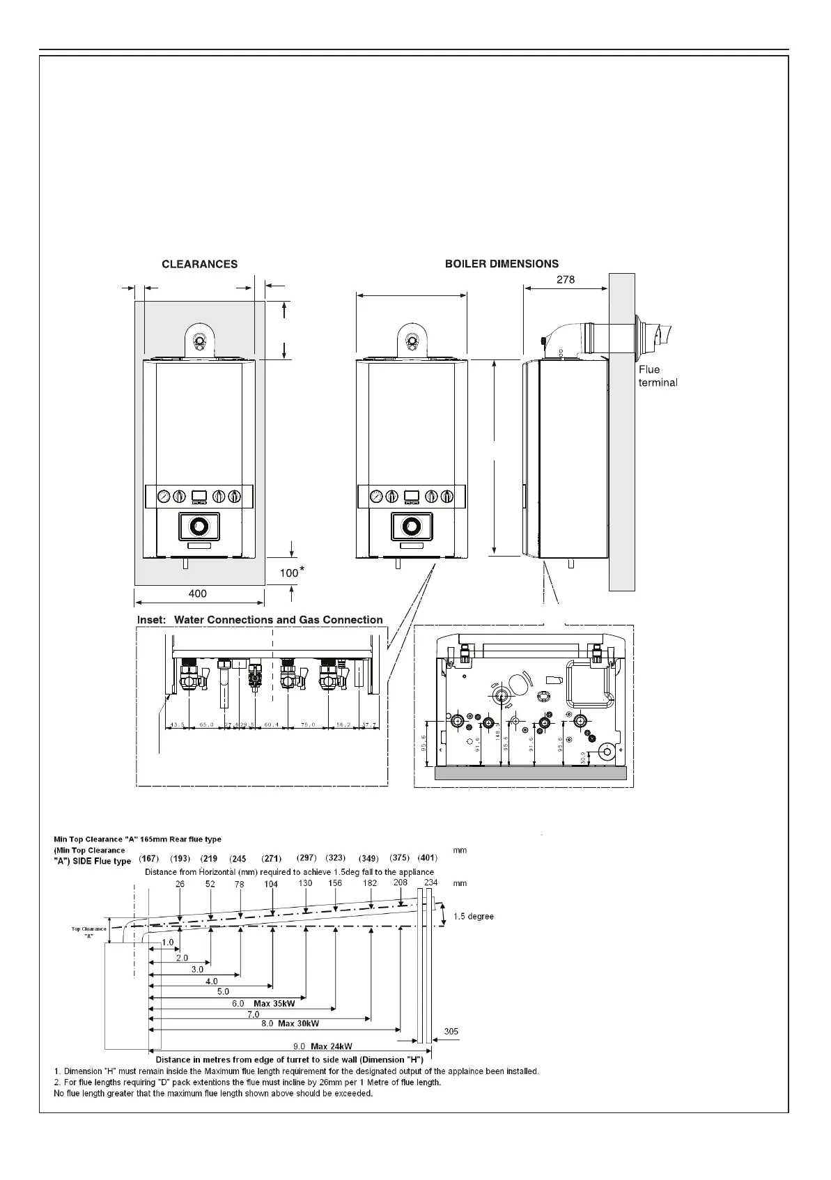
1.16 BOILER DIMENSIONS, SERVICES & CLEARANCES
all dimensions in mm
The boiler connections are made on the boiler bulkhead ttings.
Refer to Section 2.16.
The following minimum clearances must be maintained for
operation and servicing.
Additional space will be required for installation, depending upon
site conditions.
Side and Rear Flue
a. Provided that the ue hole is cut accurately, e.g. with a core
drill, the ue can be installed from inside the building where
wall thicknesses do not exceed 600mm (24”). Where the
space into which the boiler is going to be installed is less
than the length of ue required the ue must be tted from
the outside.
Installation from inside ONLY
b. If a core boring tool is to be used inside the building the
space in which the boiler is to be installed must be at least
wide enough to accommodate the tool.
Front clearance
The minimum front clearance when
built in to a cupboard is 5mm from
the cupboard door but 450mm overall
clearance is still required, with the
cupboard door open, to allow for
servicing.
* Bottom clearance
Bottom clearance after installation
can be reduced to 5mm.
This must be obtained with an
easily removable panel to provide
the 100mm clearance required for
servicing.
 Loading...