51
Installation and Servicing
SECTION 3 - SERVICING
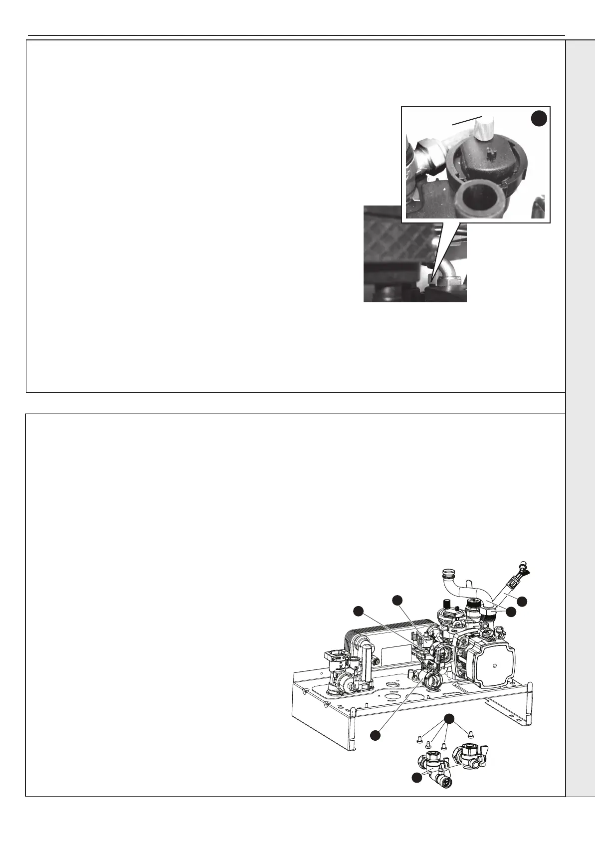
3.25 PUMP AUTOMATIC AIR VENT REPLACEMENT
1. Refer to Section 3.8.
2. Drain the boiler. Refer to Section 3.22.
3. Remove the expansion vessel. Refer to Section 3.33.
4. Firstly, increase access area by disconnecting the 22mm pipe connection
at top of pump chamber and bottom of heat exchanger and remove pipe
Refer to Section 3.26.
5. The automatic air vent head is retained in the pump body with a bayonet
connection. The air vent head and oat assembly is removed by turning
the head anti-clockwise (viewed from above) and pulling upwards.
6. Reassembly is the reverse of the above. Ensure the air vent head ‘o’ ring
seal is in place when retting and the new ‘o’ ring is tted to the return pipe
top connection.
7. Ensure the air vent cap is loose.
8. Rell the boiler. Check for leaks around the new air vent joint.
9. Check the operation of the boiler. Refer to Sections 2.22 & 2.23.
5
Dust Cap
3.26 DIVERTER VALVE BODY ASSEMBLY REPLACEMENT
11
12
14
13
16
18
17
To remove the valve body assembly:
1. Refer to Section 3.8.
2. Drain the boiler. Refer to Section 3.22.
3. Remove the condensate trap/siphon. Refer to Section 3.18.
4. Remove the electrical plug. Refer to Section 3.17.
5. Place a at bladed screwdriver in the diverter valve motor
body slot provided and ease out the motor. Refer to Section
3.17.
6. Remove the return thermistor electrical connection. Refer to
Section 3.12.
7. Remove the pump electrical connections. Refer to Section
3.28 no. 3.
8. Remove DHW Turbine electrical connection. Refer to
Section 3.20 no. 3.
9. Remove the DHW plate heat exchanger (note orientation).
Refer to Section 3.27.
10. Undo the safety valve pipe compression tting. See No.5
Section 3.24.
11. Loosen the nut above pump and rotate the pipe.
12. If required remove expansion vessel connection hose.
Refer to Section 3.32.
13. Remove the DHW inlet and CH return connection situated
beneath the boiler.
14. Remove the four torx head screws xing the return
manifold to the boiler sheet steel base.
15. Lift the manifold assembly and remove from boiler.
16. Twist and remove the DHW manifold.
17. Remove the two diverter valve body xing screws and
withdraw the diverter valve body assembly.
18. Fit the new diverter valve body assembly and replace the
two xing screws.
19. Ret the DHW manifold, t the assembly back to the boiler
and reassemble in reverse order.
20. Rell the boiler. Check that the boiler operates in both DHW
& CH modes.
SERVICING
 Loading...