31
Installation and Servicing
SECTION 2 - INSTALLATION
2.17 ELECTRICAL CONNECTIONS
Wiring should be 3 core PVC insulated cable, not less than
0.75mm
2
(24 x 0.2mm), and to BS 6500 Table 16. For IE
reference should be made to the current ETCI rules for
electrical installations.
Connection must be made in a way that allows complete
isolation of the electrical supply such as a double pole switch
having a 3mm contact separation in both poles. The means of
isolation must be accessible to the user after installation.
WARNING. This appliance MUST be earthed.
A mains supply of 230Vac ~ 50 Hz is required.
The fuse rating should be 3A. All external controls and wiring
must be suitable for mains voltage.
Wiring external to the boiler MUST be in accordance with the
current I.E.E. (BS.7671) Wiring Regulations and any local
regulations.
2.18 INSTALLER WIRING
A mains cable must be connected to a permanent live supply and
NOT switched by thermostats/programmers. To do so follow the
instructions below
Accessing the installer wiring
1. Isolate the mains supply from the boiler.
2. Remove the front panel. Refer to section 3.2.
3. Swing down the control box into the service position,
unclip and swing back the installer wiring cover and latch
into the retaining clips. Refer to Section 3.8.
All of the connections can now be readily accessed, the plugs
can be removed to aid wiring.
Note the cable strain relief system and grommets. Once any
wiring is completed, to secure the boiler, reverse the order above.
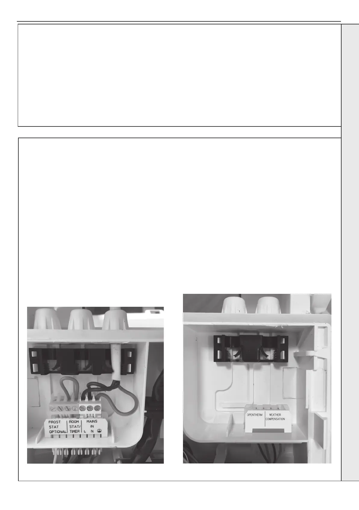
Note 1 The link wire on the 230V installer room stat/timer
connection gives a demand in conjunction with the timer option
plug inside the timer option cover (located on the front of the
new control box).
Note 2 An optional 4 way screw terminal plug is available for
the RHS installer connections as part of a number of option kits.
(Including the opentherm harness and weather compensation
kits).
INSTALLER CONNECTIONS (LHS)
Typical mains cable wiring shown.
For Room Stat / Timer see Note 1 above
INSTALLER CONNECTIONS (RHS)
INSTALLATION
 Loading...