12
Mexico Super RS 3/100 & 3/125 - Installation
INSTALLATION
6
PREPARING THE BOILER
Notes.
z Before placing the boiler in the selected position any
gas and water connections at the rear of the boiler
should be prepared, due to the possible lack of access.
z If an optional Pump Kit is to be used then it must be
fitted at this stage. Refer to separate fitting instructions
included with the kit.
z The pump may be fitted to the FLOW or the RETURN.
1. Screw the distributor tube (supplied with a 1" BSP x
INSTALLATION
28mm copper adaptor) into the selected heating return
tapping, using an appropriate jointing material.
IMPORTANT.
It is IMPERATIVE that the index mark on the distributor tube
bush is in alignment with the mark on the section boss, as
shown in Frame 3.
DO NOT disturb it when connecting subsequent pipework.
Fully pumped systems using more than 1 pump, serving
separate zones, must have a common return connection
to the distributor tube.
2. Select the desired pumped flow tapping.
3. Screw the supplied boiler thermostat pocket into the
appropriate front section tapping, using an approved
jointing material. Refer to Tables 7 and 8.
4. Connect pipe fittings to the rear tappings and plug any
unused tappings.
Note. If using iron elbows fit a short straight connector into
the boiler tapping first, to clear the casing.
Connections - as viewed at front Thermostat Position
Back Section Front Section
CH DHW
Flow Return Flow Return Top
LH LH RH RH LH
LH RH RH LH LH
RH RH LH LH RH
RH LH LH RH RH
Table 8 - Gravity Domestic Hot Water
and Pumped Central Heating
Table 7 - Fully Pumped Systems
Connections - as viewed at front Thermostat Position
Back Section Front Section
Flow Return Top
LH LH LH
LH RH LH
RH RH RH
RH LH RH
7
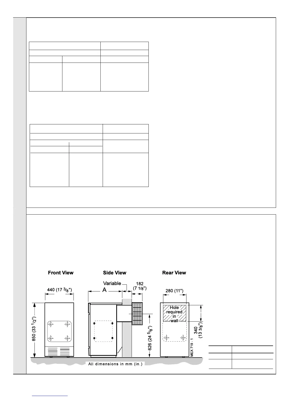
PREPARING THE WALL
1. Cut the appropriate hole in the wall for insertion of the
terminal assembly.
Notes.
a. Make good the hole on the INSIDE of the building to
the given dimensions BEFORE fitting the boiler, to facilitate
sealing between the terminal and the wall when the boiler is
in position.
b. The terminal MUST NOT come into contact with a
combustible material such as that used in non-standard
construction of timber frame and plasterboard etc.
2. Place the boiler in the
selected position.
Note. If an extension duct
D is to be fitted, this must
be done BEFORE the
boiler is placed in position.
Refer to Frame 9.
3. Make good the brickwork
around the air duct.
Boiler Dimension A
RS 3/100 533 mm (21")
RS 3/125 600 mm (23
5/8")
 Loading...