19
Mexico Super RS 3/100 & 3/125 - Installation
INSTALLATION
24
INITIAL LIGHTING
1. Turn the gas service cock to OFF and undo the union nut.
2. Remove the 4 wing nuts and withdraw the burner and
controls assembly, complete, from the boiler.
3. Invert the burner assembly and reconnect to the gas service
cock.
4. Turn the gas service cock to ON.
5. Light the pilot burner. Refer to Frame 24.
6. Test for gas soundness around the pilot burner connection,
using leak detection fluid.
7. Turn the gas service cock to OFF and return the burner and
controls assembly to the normal working position.
INSTALLATION
25
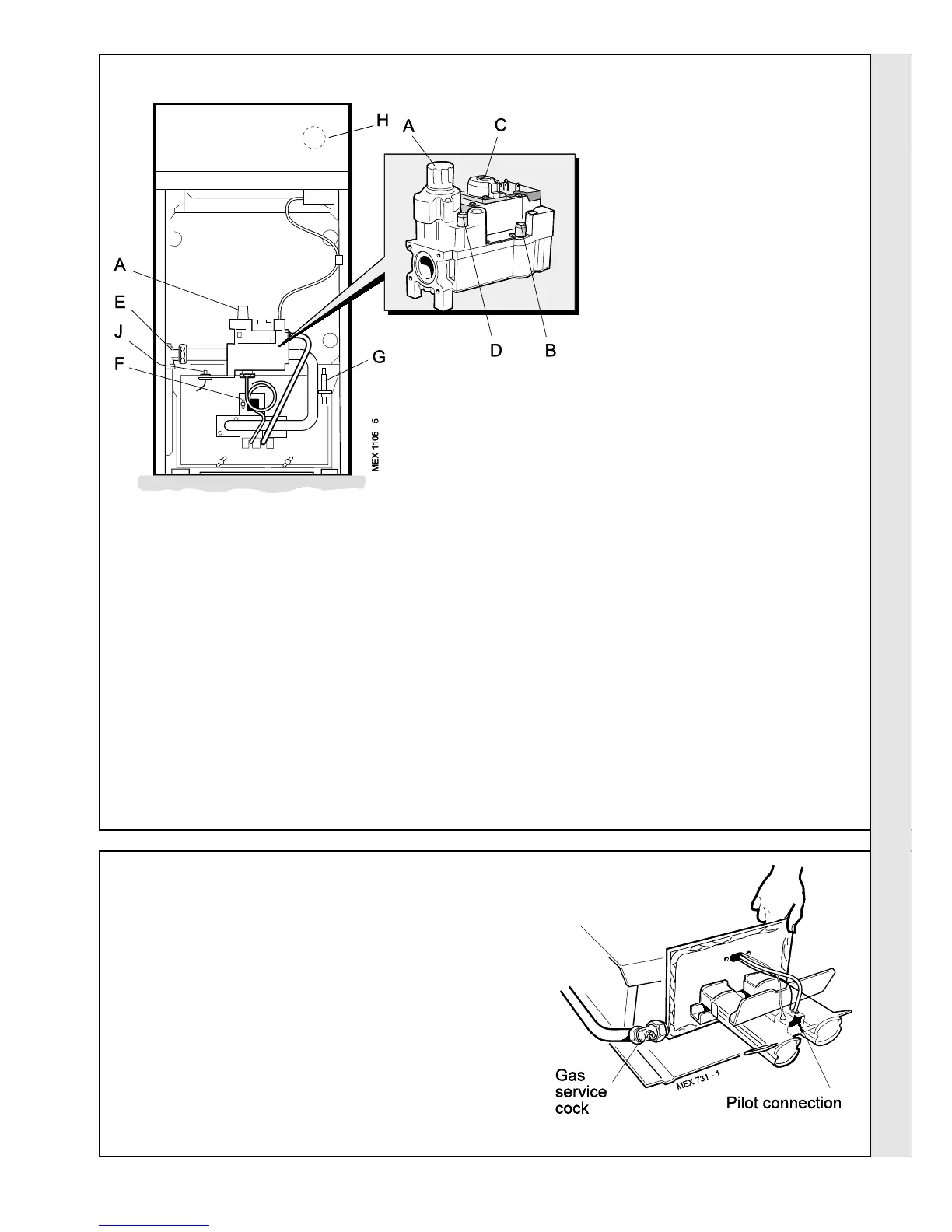
PILOT BURNER CONNECTION GAS SOUNDNESS
1. Connect the gas valve electrical leads and refit the cover.
2. Check that the gas service cock (E) is ON and that the
boiler thermostat control knob (H) is OFF.
3. Loosen the screw in the burner pressure test point (B)
and connect a gas pressure gauge via a flexible tube.
4. Turn the gas control knob (A) CLOCKWISE until
resistance is felt and then release it.
5. Push in and retain fully depressed the gas control knob
(A). Press and release the piezo unit button (G) repeatedly
until the pilot is seen to light through the sightglass (F).
6. Hold the gas control knob (A) depressed for 15 seconds
after the pilot burner has ignited, then release.
If the pilot burner fails to remain alight at this stage, repeat
the procedure detailed above but wait longer than 15
seconds before releasing the gas control knob (A).
7. Check the appearance of the pilot flame to ensure that it
Burner and controls assembly
stabilise the burner temperature. The boiler is preset at the
factory to its maximum nominal rating but can be range-
rated to suit the system design requirements. Refer to Table
2, page 3.
If the burner setting pressure requires adjustment, remove
the silver threaded protection cap on the top of the
regulator. Adjust the main burner pressure adjuster (C) until
the required main burner pressure is achieved.
Note. Continual adjustment in either direction will produce
the opposite effect.
11. If the boiler output is set to MID or MINIMUM affix the
appropriate indicator label, supplied, to the data plate (front
of baseplate).
12. Turn the boiler thermostat knob (H) to OFF.
13. Remove the pressure gauge and tube. Retighten the
screw in the pressure test point, ensuring that a gas-tight
seal is made.
envelops the tip of the thermocouple
and is approximately 25mm (1") long.
The pilot flame is factory set and no
adjustment is possible.
8. Switch the boiler thermostat control
knob (H ) to position 6 and check that
the burner cross-lights smoothly from
the pilot flame.
9. Test for gas soundness around the
boiler gas component joints, using leak
detection fluid.
10. Operate the boiler for 10 minutes to
LEGEND
A Gas control knob
B Burner pressure test point
C Main burner pressure
adjuster
D Inlet pressure test point
E Gas service cock
F Sightglass
G Piezo unit ignition
H Boiler thermostat knob
J Overheat thermostat reset
button (optional)
 Loading...