hipot.com 33
Signals on Remote I/O
REMOTE INPUT/OUTPUT
Remote Output
Output Signal Pins Description
PASS 1 and 2 The relay contact closes after detecting that the device under test passed all
tests. The connection is opened when the next test is initiated or the reset
function is activated.
FAIL 3 and 4 The relay contact closes after detecting that the device under test failed any
test. The connection is opened when the next test is initiated or the reset
function activated.
PROCESSING 5 and 6 The relay contact closes while the tester is performing a test. The connection is
opened at the end of the test.
These are normally open free contacts and will not provide any voltage or current. The ratings of the contacts are 1 AAC/250 VAC
(0.5 ADC ). When a terminal becomes active, the relay closes thereby allowing the external voltage to operate an external device.
Remote Input
Output Signal Pins Description
TEST 3 and 5 A normally open momentary switch can be wired across pins 3 and 5 to allow
remote operation of the TEST function.
REST 2 and 5 A normally open momentary switch can be wired across pins 2 and 5 to allow
remote operation of the RESET function. For safety, the front panel RESET but-
ton remains active even when a remote reset switch is connected so that high
voltage can be shut down from either location.
INTERLOCK 4 and 5 Remote Interlock utilizes a set of closed contacts to enable the tester’s output.
The output of the tester will be disabled under the following conditions:
• If the Interlock contacts are open and the TEST button is pushed
• If the interlock contacts are opened during a test (test will automatically
abort)
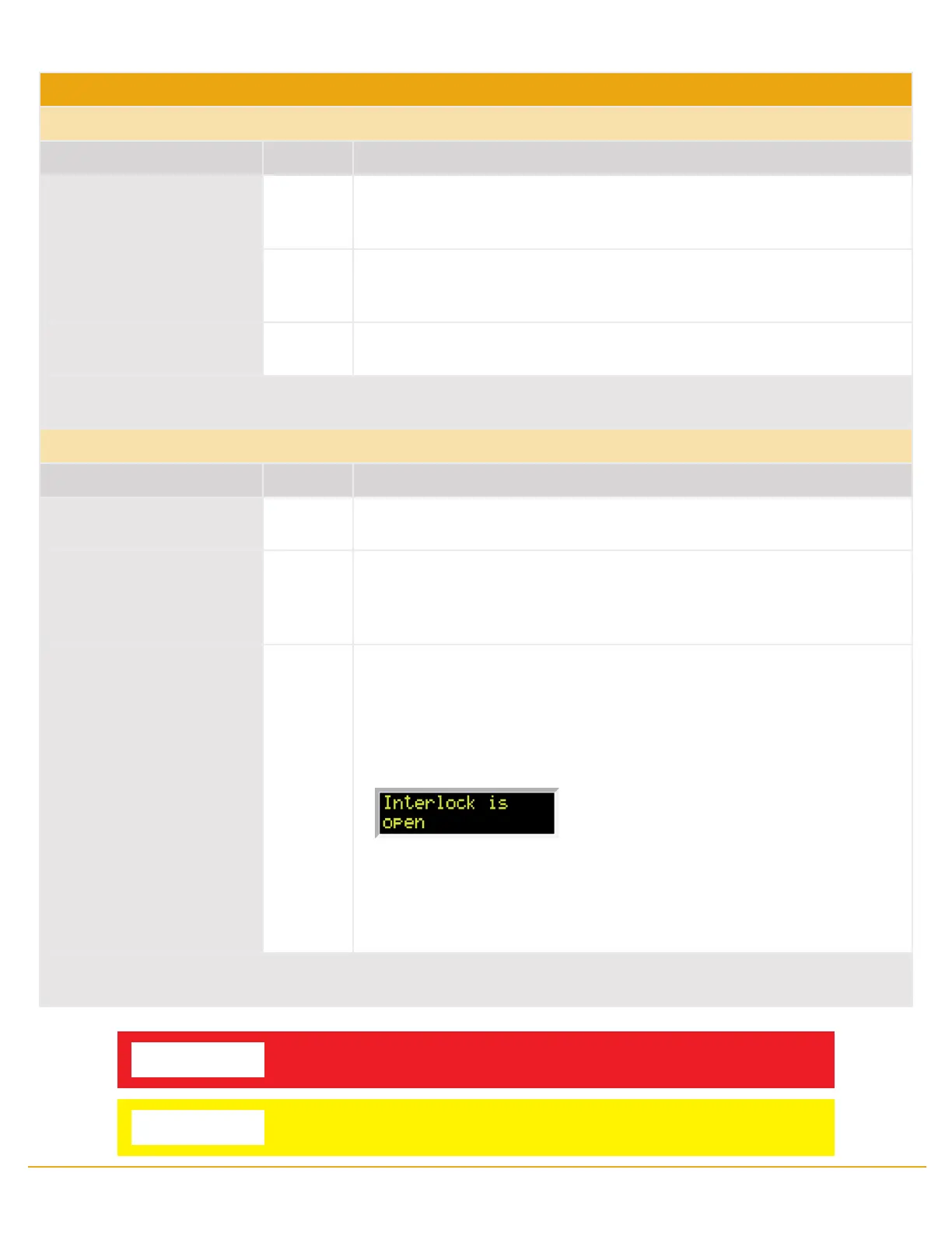
A pop-up message will be displayed on the screen:
The tester can still be used without the external interlock device as long as the
Interlock Connector (P/N # 99-10040-01 provided with unit) is plugged into
the Remote Interface, Signal Input port. If there is nothing connected to the
Remote Interface, Signal Input port to provide a connection to the interlock,
the tester will not perform tests.
When the PLC Remote mode is ON, the tester will respond to simple switch or relay contacts closures. When the PLC Remote function
is ON the TEST button on the front panel will be disabled.
WARNING
ACTIVATING TEST PROGRAM FUNCTIONS THROUGH THE REMOTE CONNECTOR SELECTS
THE MEMORY AND STARTS THE TEST THAT IS PRE-PROGRAMMED INTO THAT MEMORY.
CAUTION
Do not connect voltage or current to the signal inputs. Applying voltage to the signal
input could result in damage to the control circuitry.
 Loading...