User Manual 4-1 V2.0
Application Kit TC3X7 ADAS V2.0 2018-06
Application Kit Manual TC3X7 ADAS
Hardware: Application Kit TC3X7 ADAS V2.0
Application Kit Configuration
4 Application Kit Configuration
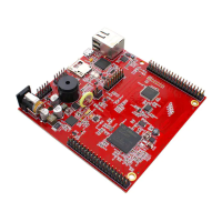
The Application Kit has a fixed configuration which can be sligthly changed. For locating components see
Figure 7-5 and Figure 7-6.
4.1 Default Pad State
The default pad state is that the internal pull-up devices on the I/O pins are enabled. This can be changed by
assembling resistor R143 with 2K2 (drive P14.4 / HWCFG6 low). If the resistor R143 is assembled then all I/O pins
are in tristate. Additonal you must make sure that R134 is also assembled with 10K that the EVRC is enabled
properly in this case.
4.2 Bootmode
The bootmode is fixed set to Start-up mode is selected by Boot Mode Index. This can be changed to boot from
pins and Internal Start from Flash by removing resistor R133 (drive P14.3 / HWCFG3 high) and assembling resistor
R142 with 2K2 (drive P14.3 / HWCFG3 low). If the I/O pins are set to tristate per default (R143 assembled) then you
must assemble also resistor R134 and resistor R272 with 10K to set the HWCFG pins to proper values.

 Loading...