User Manual 5-1 V2.0
Application Kit TC3X7 ADAS V2.0 2018-06
Application Kit Manual TC3X7 ADAS
Hardware: Application Kit TC3X7 ADAS V2.0
Signal (on board used) Description
5 Signal (on board used) Description
For more information about the signals please see the user manual/datasheet for TC3X7 and/or the schematics
of the board.
All not mentioned signals are not used on the board and can be used outside if they are connected to the IO
Connectors see Figure 6-1. Optional marked signals are used only if they are connected (default is that they are
not used on the board).
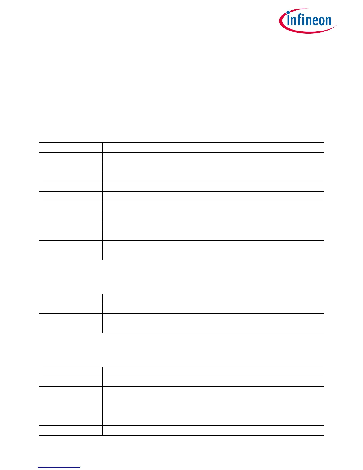
5.1 Power Signals
5.2 Reset Signals
5.3 Config Signals
Table 5-1 Power Signals
Short name Description
VCC_IN Supply Input (3,5V...40V)
VIN Input Voltage of Power Supply Device
GND Ground
+3V3 Supply Voltage (3,3V)
+5V Supply Voltage (5V)
VDD Core Supply Voltage (1,25V)
VDDM ADC Analog Part Supply Voltage (5V or 3,3V selectable via 1R resistors)
VAREF1 ADC Reference Voltage 1 (5V or 3,3V selectable via 4R7 resistors)
VAREF2 ADC Reference Voltage 2 (5V or 3,3V selectable via 4R7 resistors)
VDD_USB Supply Voltage from USB (5V)
VDD_FT Supply Voltage FT2232HL device (3,3V)
Table 5-2 Reset Signals
Short name Description
/PORST Power On Reset
/ESR0 External Service Request 0 (Hardware Reset)
/ESR1 External Service Request 1 (Non Maskable Interrupt)
Table 5-3 Config Signals
Short name Description
P14.5 HWCFG1 (EVR33OFF)
P14.2 HWCFG2 (EVRCOFF)
P14.4 HWCFG6 (Pins in tristate / Pins with pull-up)
P14.3 HWCFG3 (Boot from pins / Boot from Flash BMI)
P10.5 HWCFG4 (Boot from internal flash)
P10.6 HWCFG5 (Boot from internal flash )

 Loading...