User Manual 6-1 V2.0
Application Kit TC3X7 ADAS V2.0 2018-06
Application Kit Manual TC3X7 ADAS
Hardware: Application Kit TC3X7 ADAS V2.0
Connector Pin Assignment
6 Connector Pin Assignment
The Application Kit will be shipped with two 40 pin male (plug) connectors on top layer with a standard grid of
2,54mm.
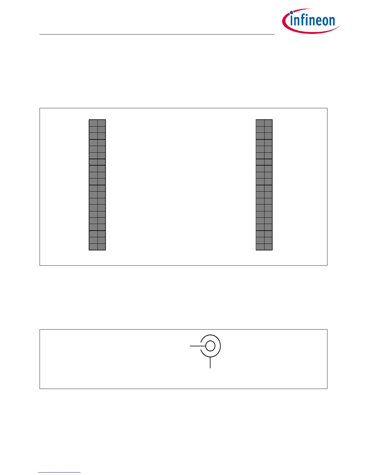
6.1 I/O connectors TC397 ADAS
Figure 6-1 IO connectors for TC397 - Pinout
Note: VCC_IN is connected to X102 and X103 with a 0R resistor which is not assembled by default to avoid
shortcut to 3,3V in case of measurement on the connector. If VCC_IN needed on X102 and X103 then
assemble R113 with a resistor 0R size 0805. Pin 1 of X102 and X103 are always connected together.
Power connector pinout
Figure 6-2 Power connector pinout (Roka 520 2550)
(VCC_IN) 1 2 +3V3 P14.5 40 39 P14.4
GND 3 4 GND P33.10 38 37 P33.9
P21.2 5 6 P21.3 P15.7 36 35 P15.6
P14.8 7 8 P14.7 P15.5 34 33 P15.4
P14.6 9 10 P20.0 P15.8 32 31 P15.2
P21.41112P21.5 P22.33029P22.2
P02.01314P02.1 P22.12827P22.0
P02.2 15 16 P02.3 P33.11 26 25 P23.4
P02.41718P02.5 P23.32423P23.2
P02.61920P02.7 P23.12221P23.0
P02.82122P00.0 P33.62019P33.8
P00.1 23 24 P00.2 P33.12 18 17 P33.1
P00.32526P00.4 P33.21615P33.3
P00.52728P00.6 P33.41413P33.5
P00.72930P00.8 AN0 1211 AN8
P00.9 31 32 P00.10 AN2 10 9 AN3
P00.11 33 34 P00.12 AN11 8 7 AN13
AN19 35 36 AN18 AN20 6 5 AN21
AN17 37 38 AN16 GND 4 3 GND
AN25 39 40 AN24 +3V3 2 1 (VCC_IN)
X102X103

 Loading...