Installation Manual
32 Installation
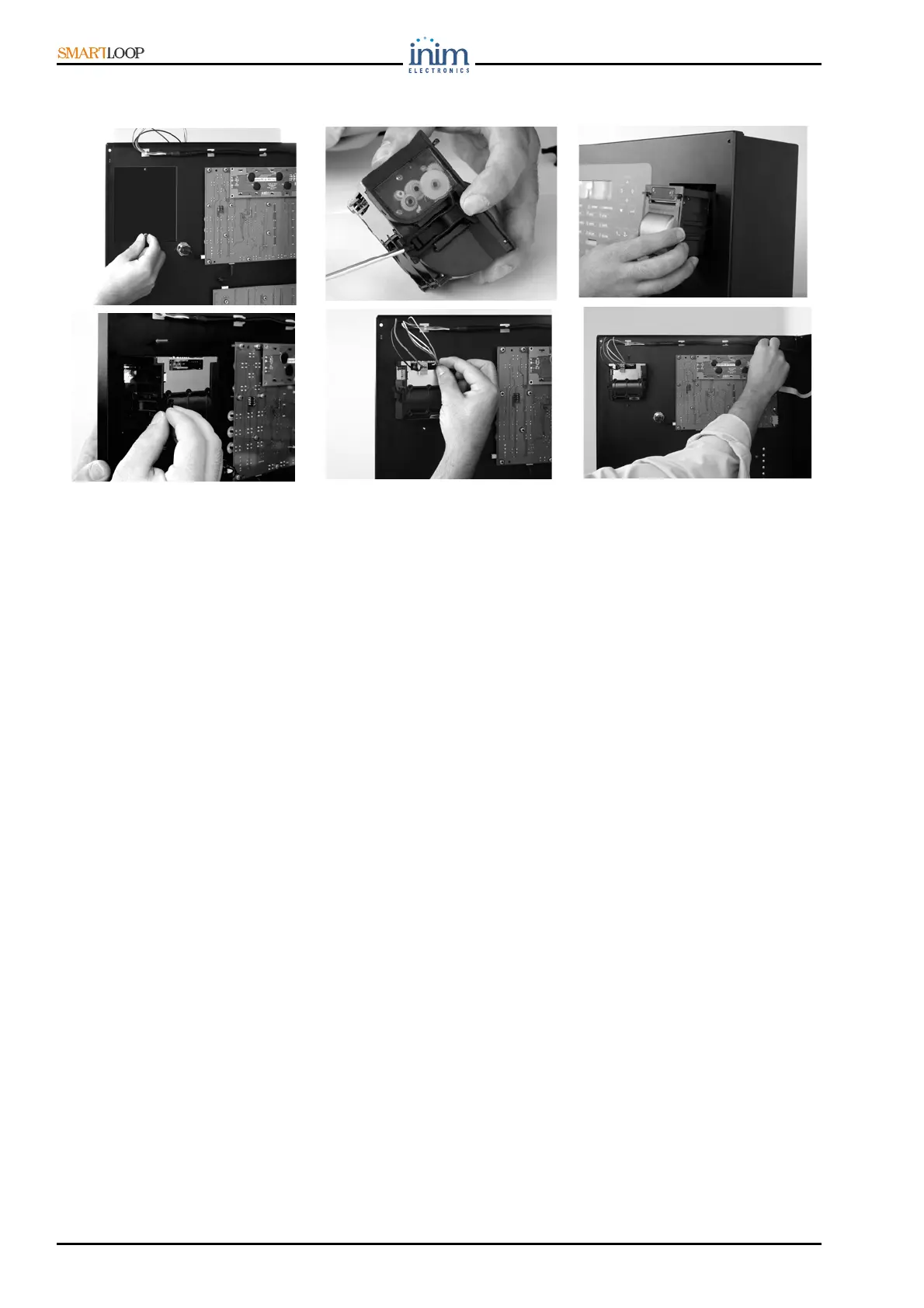
6.4 Connecting the SmartLoop/PRN printer module
Figure 26 - Connecting the SmartLoop/PRN printer module
1. Remove the nuts from the soldered screws on the plate [refer to Figure 26 - 1], then remove the
plate.
2. Slide out the side locks (fitted flush with the sides of the printer) [refer to Figure 26 - 2].
3. Working from the front of the cabinet (door closed), insert the Printer into its location [refer to
Figure 26 - 3].
4. Holding the printer module firmly in position, open the door and, using the side locks, secure the
module to its location [refer to Figure 26 - 4].
5. Connect the 2 wires and the connector [refer to Figure 26 - 5] to the terminals Figure 20 - 1 and
2. Connect the SmartLoop/PRN printer module to the motherboard (Figure 5 - connector 13].
6. Locate the adhesive wire saddles (included in SmartLoop/PRN kit), above the display board as
indicated in the figure. Refer to “Figure 26 -”. Push the cable into the wire saddles (included in
SmartLoop/PRN kit).
3
2
1
4
5
6
 Loading...