Installation Manual
Connections 41
7.19.2 Voltage testing
The panel continuously monitors the battery voltage. If the voltage drops below the 22.8 V, the panel
will signal the event on the respective Fault LED and on the display. The event will end when the
voltage restores to over 24.6 V.
7.19.3 Deep discharge monitoring
If the battery voltage drops below 18 V, the panel will disconnect them in order to avoid battery
damage. If this occurs, the PL terminal will close to ground thus generating a “Shutdown” signal.
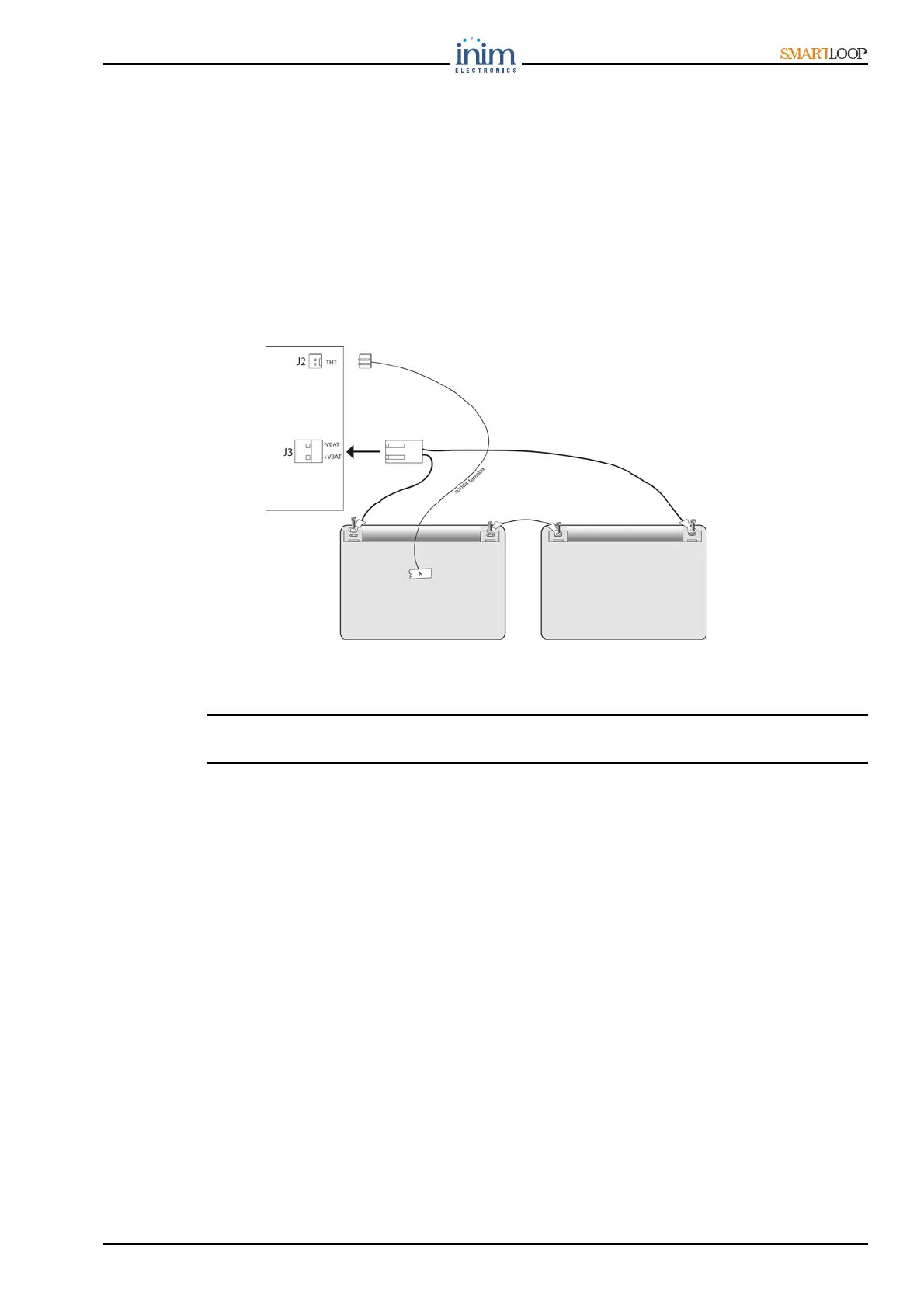
7.19.4 Connecting the batteries
1. Locate the batteries in position [figure 40-1], as shown in the following figure.
2. Using the battery terminal eyelet wires (included), insert the battery terminal bolt through the
spacer washer and battery terminal eyelet tab, as per following figure.
Figure 38 - Connecting the batteries
7.20 Connecting the Thermal Probe
Attention: In order to validate the IMQ-SISTEMI DI SICUREZZA certification and comply with EN
54-4 requirements, installation of a thermal probe is essential.
This panel has an on-board connector [figure 5-16] for a ProbeTH thermal probe (accessory item).
The ProbeTH thermal probe regulates the battery-charge system by interacting with the battery
temperature, this operating method avoids battery damage.
1. Plug the ProbeTH thermal probe into the connector [figure 5-16] on the motherboard. Disconnect
the batteries (if already connected).
2. Using a strip of strongly-adhesive insulating tape (not included), attach the Thermal probe to one
of the batteries, in such way as to a provide optimized heat-transfer measurements.
3. Using a thermometer, measure the probe temperature.
4. Using the following graph (Charge voltage in relation to Battery temperature), find the optimal
value of the charge voltage.
5. Using a voltmeter, measure the voltage on the AUX terminals [figure 5-23].
6. Using the trimmer [figure 40-2] on the switching battery supply module [figure 40-3], adjust the
voltage to the value found on the graph.
 Loading...