Installation Manual
48 Troubleshooting
- Check that the flashing Loop transmission LED corresponds to the respective loop settings. If the
LED does not correspond, check the loop parameters.
• Loop return LED -Reception
The green LED of each loop will blink each time an interrogated device responds.
If this LED is On solid, it means the device response has been interrupted by an anomalous current
flow through the conductive path between the two poles of the loop.
- Ensure that only the system devices are connected to the loop.
9.3 Repeater Fault
Missing Repeaters (the panel is unable to find some of the connected Repeater panels)
• Check that the Repeater addresses have been set properly (check the respective DIP switches, refer
to Figure 41 - DIP switch settings).
• Check the integrity of the wiring and the connection polarity.
• Check that the EOL jumper is set to EOL position ONLY on the last Repeater connected to the BUS.
• Using a multimeter or similar tool for the electrical measurements:
- Measure the voltage across the +24 V and GND terminals of the RS485 BUS. If the voltage is
below 20 V, the resettable protection fuse is open, therefore, the current draw of the devices
connected to the BUS is excessive.
- Disconnect the devices connected to the BUS one at a time until you find the cause.
9.4 Battery Fault
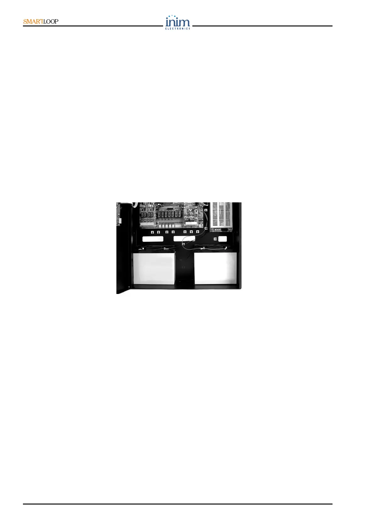
Figure 44 - Batteries
9.4.1 No battery
The batteries are either not connected or have failed the battery efficiency test.
Allow them to recharge for several hours.
• If the trouble persists, disconnect them from the panel and, using a multimeter or similar tool,
measure them separately. If only one of the batteries is below 12.5 V:
- Replace the battery concerned and allow it to recharge for several hours until fully charged.
• If both batteries are below 12.5 V .13 V: Replace both batteries and allow them to recharge for
several hours until fully charged.
• If the battery is equipped with a thermal probe:
- Check that the voltage corresponds to the value calculated using the graph (paragraph 7.19.4
Connecting the batteries). If the voltage is different, rectify it to 13.8 V by means of the trimmer
[Figure 40 -2].
9.4.2 Low battery (insufficient voltage)
This fault warning occurs only when the primary power supply (230 Vac Mains) fails. This condition
must be cleared before the batteries get too low and are unable to power to the system.
 Loading...