-25-
AC800 Series Intelligent Machine Controller Hardware User Guide 5 Wiring
No. Category Description
1 Category I Ethernet and EtherCAT interfaces
2 Category II Low-speed digital communication signals (RS232 and RS485) and DI/DO signals
3 Category III Low-voltage AC power distribution cable or DC power cable (such as DC 24 V power
cable for a switching power supply)
4 Category IV Input and output cables, welding machine cables, and power converter power cables
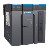
Keep a certain distance between dierent types of cables. For cables below 30 m, the minimum distance
allowed is shown in the gure below.
*
**
***
*7
NN NN NN
NN
NN
NN
Figure 5-3 Distances between dierent types of cables
◆ If two cables run parallel for an extended length, increase the distances accordingly.
◆ You can also install spliced shielding plates between dierent types of cables. To reduce
cross interference, route all cables as closely as possible to the grounded structural
components of the cabinet, such as the cabinet's mounting plate or rack components.
5.1.3 Installation of the Filter
If the controller is subject to a strong interference source (such as an AC drive), it is recommended to use
an additional noise lter to suppress the interference.
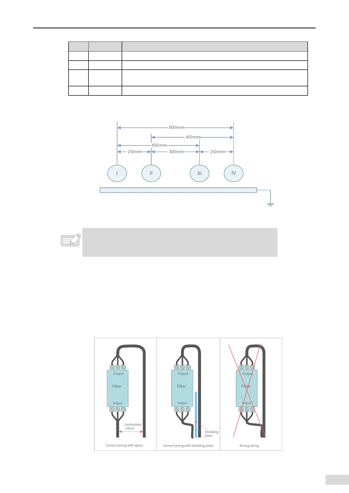
The lter should be installed as close as possible to the power supply of the controller. Fix the lter to
the conductive backplane through screws, and protect the area around the screws with paint to ensure
reliable grounding. The outgoing and incoming cable for the lter should be routed separately to avoid
noise coupling on the cable.
0VUQVU
'JMUFS
*OUQVU
6OTIJFMEFE
DN
0VUQVU
'JMUFS
*OUQVU
0VUQVU
'JMUFS
*OUQVU
4IJFMEJOH
QMBUF
$PSSFDUXJSJOHXJUITQBDF
$PSSFDUXJSJOHXJUITIJFMEJOHQMBUF 8SPOHXJSJOH
Figure 5-4 Filter installation

 Loading...