-24-
5 Wiring
AC800 Series Intelligent Machine Controller Hardware User Guide
5 Wiring
5.1 Wiring Instructions
This section describes the precautions for wiring the controller.
5.1.1 Grounding
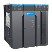
A ground point is set on the power terminal of the controller and the rear earhook ( ). Choose one of the
grounding points as needed, and ground the controller with a grounding wire that is as thick and short as
possible (less than 30 cm). It is recommended to use the grounding point on the rear earhook as possible.
A wing nut is used for grounding, with a tightening torque of 0.55–0.8 N.m:
1-wing nut; 2-grounding cable; 3-Grounding screw
Figure 5 -1 Grounding diagram
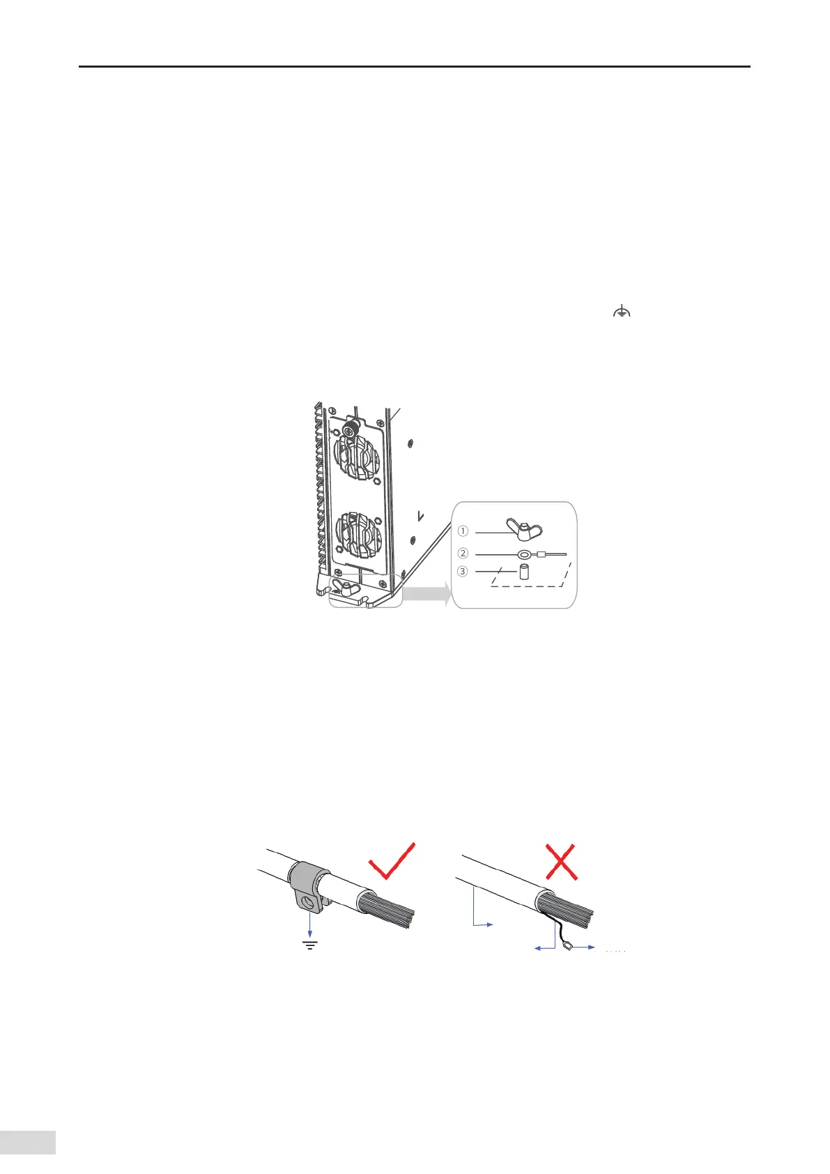
Grounding of shielded cable
Shielded cables must be used for communication signal cables. Ground as close to the module as possible
so that the cable is not interfered with by electromagnetic induction. The exposed shield of the shielded
cable must touch the grounding point as much as possible to ensure good contact.
Do not solder a PVC wire to the shield of the shielded cable for grounding. This will increase the high
frequency impedance and attenuate the shielding eect. The shield of the communication signal cable
needs to be grounded at both ends.
17$DBCMF
$POOFDUPS
4IJFMEFEDBCMF
Figure 5-2 Grounding of shielded cable
5.1.2 Requirements
Low-voltage cables (< 1 KV) are generally divided into four types. Only cables of the same type can be
put together to form a cable harness. Cables of dierent types should be separated and should not be
crossed. If cross cannot be avoided, cross cables perpendicularly.

 Loading...