- 134 -
B.3 Parameter Setting on Master Drive
•
Multi-pump mode 1 (A2-03 = 0)
The parameter setting is simple. For all servo drives, allocate a DI terminal for the 50# function and set it to
ON.
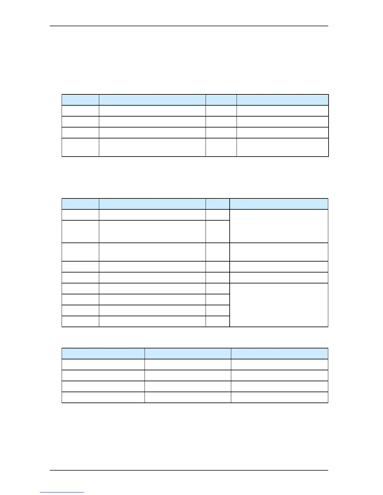
Function Code Parameter Name Setting Description
A2-01 CAN communication address 1 -
A2-03 Multi-pump mode 1 0 -
F4-** Multi-pump control enabled 50 Short DI5 to COM directly.
F5-02 Relay on the control board (T/A2-T/C2) output
selection
25 Slave alarm output (normally-open)
•
Multi-pump mode 2 (A2-03 = 1)
The servo drive with address 1 must be the master pump. A maximum of four combined distributed ow control
can be implemented. The related parameter settings are as follows:
Function Code Parameter Name Setting Description
F4-** Slave pump address selection terminal 1 53 In multi-pump distributed ow control,
these parameters are used to set which
slave pumps the master pump selects for
convergent ow.
F4-** Slave pump address selection terminal 2 54
F5-02 Relay on the control board (T/A2-T/C2) output
selection
25 Slave alarm output (normally-open)
A2-01 CAN communication address 1 -
A2-03 Multi-pump mode 1 1 -
A2-04 CAN slave address 1 0 Together with the two DI terminals set
for the 53# and 54# functions, the four
combined distributed ow control can be
implemented.
A2-05 CAN slave address 2 0
A2-06 CAN slave address 3 0
A2-07 CAN slave address 4 0
•
Slave pump address DI input selection
Setting of DI Set for 54# Function Setting of DI Set for 54# Function CAN Slave Address Selection
0 0 A2-04: CAN slave address 1
0 1 A2-05: CAN slave address 2
1 0 A2-06: CAN slave address 3
1 1 A2-07: CAN slave address 4

 Loading...