- 135 -
•
Description of slave pump address setting
The LED display of the slave pump address setting is as follows:
Note
•
The numbers in the LED display correspond to the slave pump address station No.
•
If the nixie tube of a number is ON, it indicates that the slave pump of the address station No.
•
The IS580 supports the setting of a total of 15 slave pump addresses.
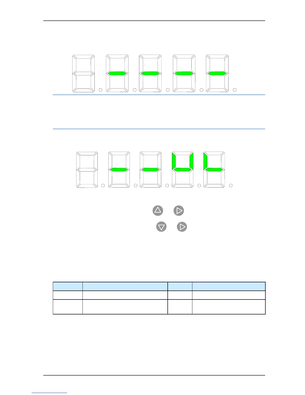
For example, 1# is the master pump. The setting of slave pump addresses in A2-04 is shown in the following
gure, indicating that 1# is the master pump and works with slave pumps 2#, 3# and 4#.
The key operation of the slave pump address is described below:
-
The address of slave pumps 1# to 8# is set by and .
-
The address of slave pumps 9# to 15# is set by and .
B.4 Parameter Setting on Slave Drive
•
Multi-pump mode 1 (A2-03 = 0)
The following table lists the parameter setting of the slave drive. Perform the same parameter setting as you
do in the common servo pump mode.
Function Code Parameter Name Setting Description
A2-01 CAN communication address > 1 Slave drive
F4-** Multi-pump control enabled 50 Slave pump may switch over to master
pump control.
If the slave pump switches over to master pump, disconnect the DI terminal set for the 50# function of the
slave pump.

 Loading...