- 30 -
Type Terminal Name Description
Analog output
AO1-GND Analog output 1
Voltage or current output is decided by jumper J4.
Output range: 0–10 V/0–20 mA
12-bit resolution, correction accuracy 1%, maximum load
resistance value ≤ 500 Ω
AO2-GND Analog output 2
Voltage or current output is decided by jumper J6.
Output range: 0–10 V/0–20 mA
12-bit resolution, correction accuracy 1%, maximum load
resistance value ≤ 500 Ω
Relay output
T/A1-T/B1 NC terminal
Contact driving capacity:
250 VAC, 3 A, COSφ = 0.4; 30 VDC, 1 A
T/A1-T/A3-T/
C1-T/C3
NO terminal
Auxiliary
interface
CNR1
External operation
panel interface
Connect to the external operation panel.
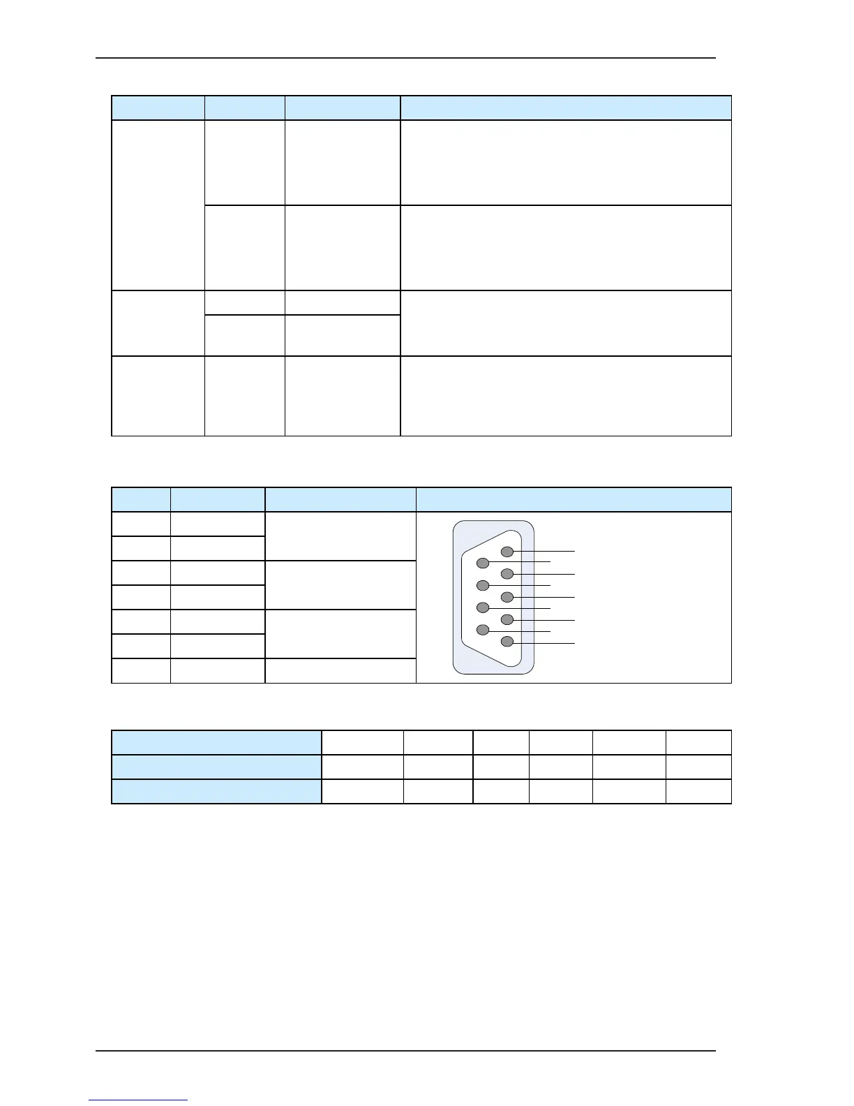
3.5 Description of PG Card Terminals on the IS580
No. Name Description Pin Denition
1 REF-
Excitation signal
2 REF+
3 COS+
COS feedback signal
4 COS-
5 SIN+
SIN feedback signal
9 SIN-
6–8 - -
The following table denes the matching signal cables for the IS580 (for reference only)
Signal Denition REF- REF+ COS+ COS- SIN+ SIN-
Color of Matching Encoder Cable Yellow-white Red-white Red Black Yellow Blue
Corresponding PG Card and DB9 Pin 1 2 3 4 5 9

 Loading...