Chapter 10 Appendix IS580 User Manual
- 140 -
In this combination, the 1# pump and 3# pump are the master pumps. The slave pump changes and the address of
the slave pump needs to be set. The slave pump of the 1# master pump is 2# pump. The setting of the slave pump
address in A2-05 is as follows:
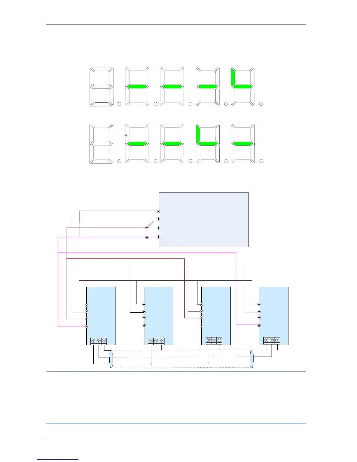
The slave pump of the 3# master pump is 4# pump. The setting of the slave pump address in A2-05 is as follows:
■
Combination 2: 3+1 combination for distributed ow control
Figure B-9 Wiring of 3+1 combination for distributed ow control
Slave
drive 2#
CGNDCANH
CANL
CGNDCANH
CANL
CGNDCANH
CANL
CGNDCANH
CANL
Host
computer
Distributed flow signal 1 DO
COM
Distributed flow signal 1 DO
RUN enabled DO
Master
drive 1#
Slave
drive 3#
Slave
drive 4#
COM
RUN enabled DI
53# DI
COM
RUN enabled DI
53# DI
COM
RUN enabled DI
53# DI
COM
RUN enabled DI
53# DI
54# DI
54# DI 54# DI 54# DI
Note
•
The host computer provides the distributed ow signal. Connect the distributed ow signal to the DI
terminal set for the 54# function of the master drive. The master pump identies the slave pump address
through the 54# DI signal. The slave pump switches over to the master pump and identies the slave
pump address by using the 54# DI signal.
•
Disconnect the DI terminal set for the 53# function in the second combination.

 Loading...